68
160XT 180XT 210XT
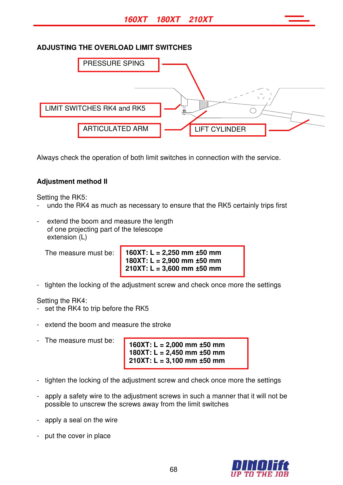
ADJUSTING THE OVERLOAD LIMIT SWITCHES
Always check the operation of both limit switches in connection with the service.
Adjustment method II
Setting the RK5:
- undo the RK4 as much as necessary to ensure that the RK5 certainly trips first
- extend the boom and measure the length
of one projecting part of the telescope
extension (L)
The measure must be:
- tighten the locking of the adjustment screw and check once more the settings
Setting the RK4:
- set the RK4 to trip before the RK5
- extend the boom and measure the stroke
- The measure must be:
- tighten the locking of the adjustment screw and check once more the settings
- apply a safety wire to the adjustment screws in such a manner that it will not be
possible to unscrew the screws away from the limit switches
- apply a seal on the wire
- put the cover in place
160XT: L = 2,250 mm ±50 mm
180XT: L = 2,900 mm ±50 mm
210XT: L = 3,600 mm ±50 mm
160XT: L = 2,000 mm ±50 mm
180XT: L = 2,450 mm ±50 mm
210XT: L = 3,100 mm ±50 mm
LIMIT SWITCHES RK4 and RK5
PRESSURE SPING
LIFT CYLINDER
ARTICULATED ARM
Courtesy of Crane.Market