Dobot CR Series User Guide
Issue V1.1 (2023-04-27) User Guide Copyright © Yuejiang Technology Co., Ltd.
46
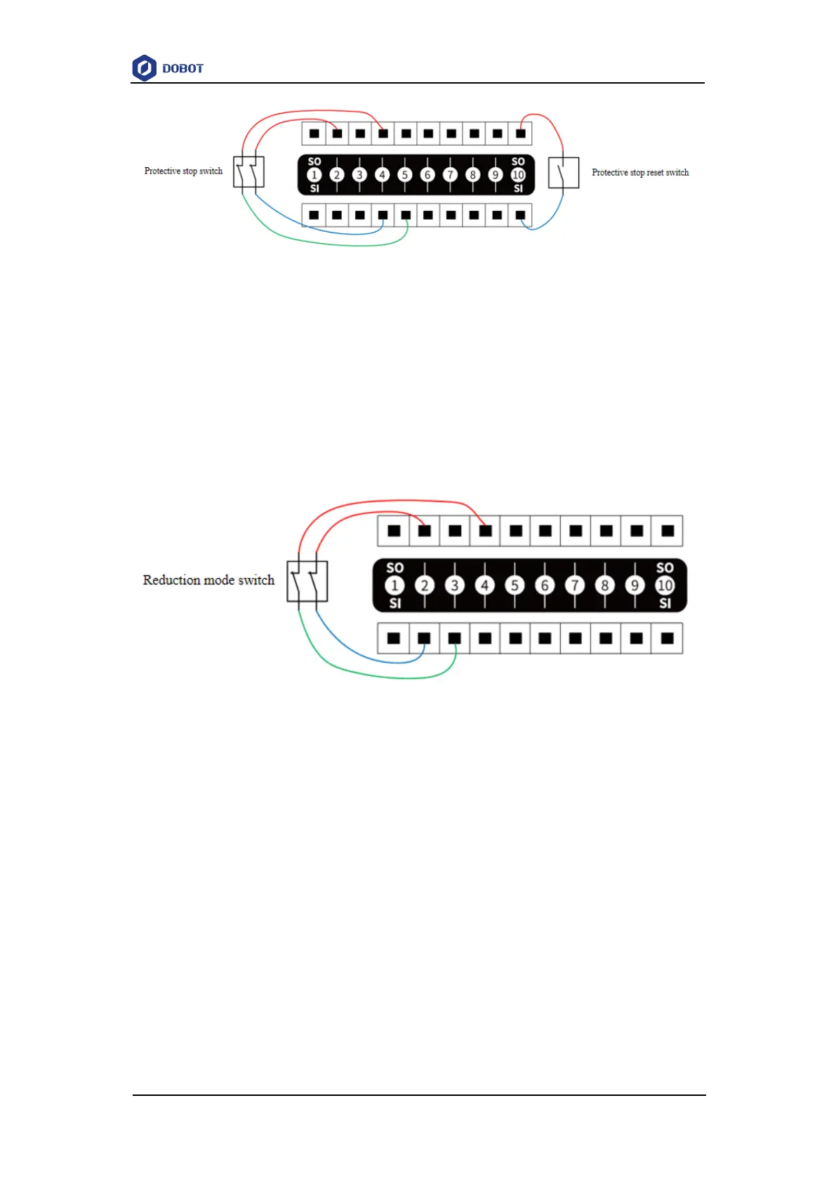
Figure 6.12 SI connected to protective stop device (with reset switch)
Reduction mode interface
Reduction mode interface is used to control the robot into reduction mode. In reduction mode,
the motion parameters of the robot arm (joint speed, TCP speed) are limited within the range of the
user-defined reduction mode.
The default input of reduction mode is the normally closed signal of high level, and low-level
input triggers the robot to enter the reduction mode. If the high-level input is restored, the robot exits
the reduction mode and enters the normal mode.
Figure 6.13 SI connected to reduction mode switch
Automatic operation confirmation interface
You need to confirm the automatic operation interface before the robot enters the automatic
operation mode. The default automatic operation input is the normally open signal of high power,
and rising edge triggers the robot to start the automatic mode confirmation.
If you configure SI04 and SI05 as automatic operation confirmation input, the wiring of
connecting automatic operation confirmation switch is shown below (SO02 and SO04 are 24V).
Emergency stop state output interface
The emergency stop state output interface is used to confirm whether the robot enters the
emergency stop state. In emergency stop state, the output voltage is low level, and in non-emergency
stop state, the output voltage is high level.
If you configure SO03 as emergency stop state output, the wiring of connecting external load
is shown below. The other end of the load can be connected to any 0V interface on the general I/O