Note regarding the pressure control:
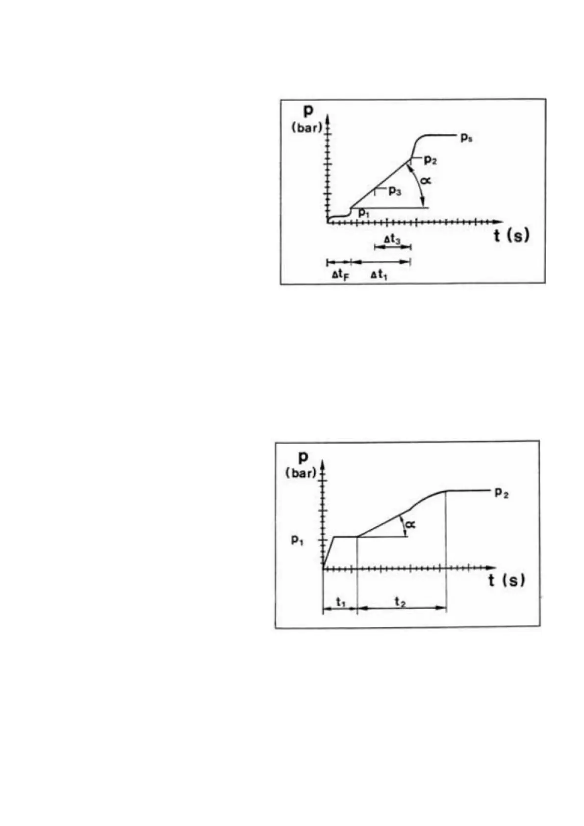
Diagram 1 (Basic diagram)
Pressure-control curve gear case
p = Pressure in box
t - Time in seconds
p1 =Modulation start
p2 =Modulation end
p3= Modulation start only in dependence
with 2-stage pressure control valve
ps =Control pressure
Δ tF =Filling time
Δ t1 = Modulation time
Δ t3 =Modulation time in dependence with
2-stage pressure control valve
Diagram 2 (Basic diagram)
Pressure-control curve WK
p' • Modulation start
p - Modulation end
t1 - Filling time
t2 - Modulation time
ATTENTION:
The pressure-control curve is different according to the Transmission Version, resp. the vehicle type and will be adjusted by
means of corresponding shims and diaphragms (optional)'
Transmission and Torque Converter SPC000007
Page 13