General Description
Structure of Travelling Brake:
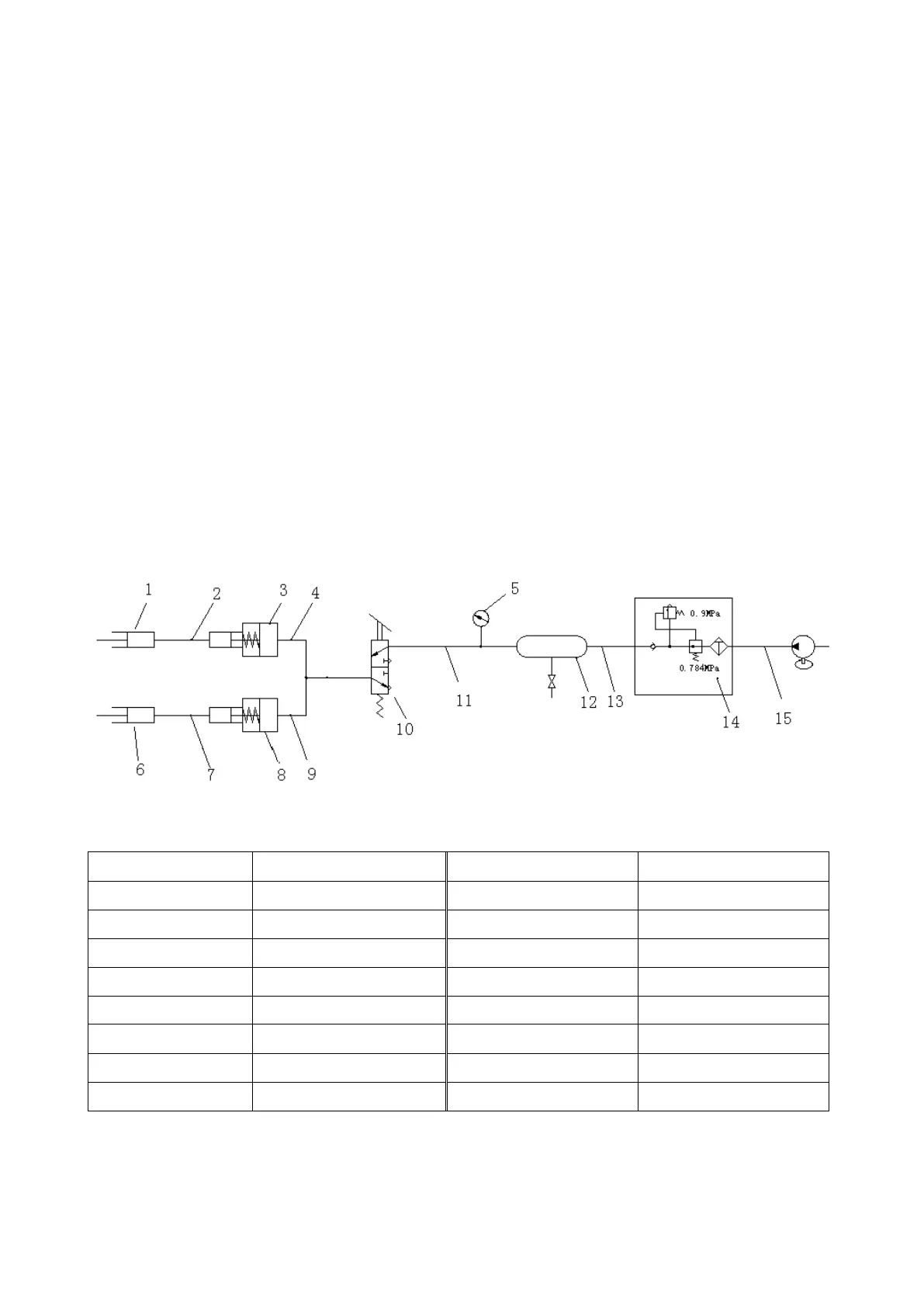
It usually includes air compressor, oil-water separation combination valve (oil-water separator, pressure
control valve), air tank, pneumatic brake valve, air booster pump and caliper disc brake. If it is equipped with
emergency braking function, it usually also includes emergency and stopping brake control valve, brake air
chamber, quick release valve. In air circuit of brake system, there are some other accessories, such as
switch of brake light, switch of power off, etc.
Working Principle of Travelling Brake:
Compressed air is output from air compressor driven by engine, and enters into air tank through oil-
water separation combination valve (oil-water separator, pressure control valve). When air pressure in air
tank reaches the highest braking pressure (usually around 0.784MPa) of brake system, pressure control
valve will close the exit going to air tank, open load discharging mouth and discharge the compressed air
from air compressor to the air directly. When compressed air in air tank reaches the lowest pressure (usually
around 0.71MPa) of brake system, pressure control valve will open the exit going to air tank, and close load
discharging mouth to let compressed air from air compressor into air tank for supplementation until the
compressed air in air tank reaches the highest working pressure of brake system.
Following is the fundamental diagram:
Brake System SPC000021
Page 3