1.3.3.2 REASSEMBLY
see also illustrated Table, Page
73 and 74 !
NOTE :
Check all components for damage and renew if
necessary !
Check free travel of the moving parts in the housing
prior to the installation !
Spools can be exchanged individually !
Oil components prior to the reassembly !
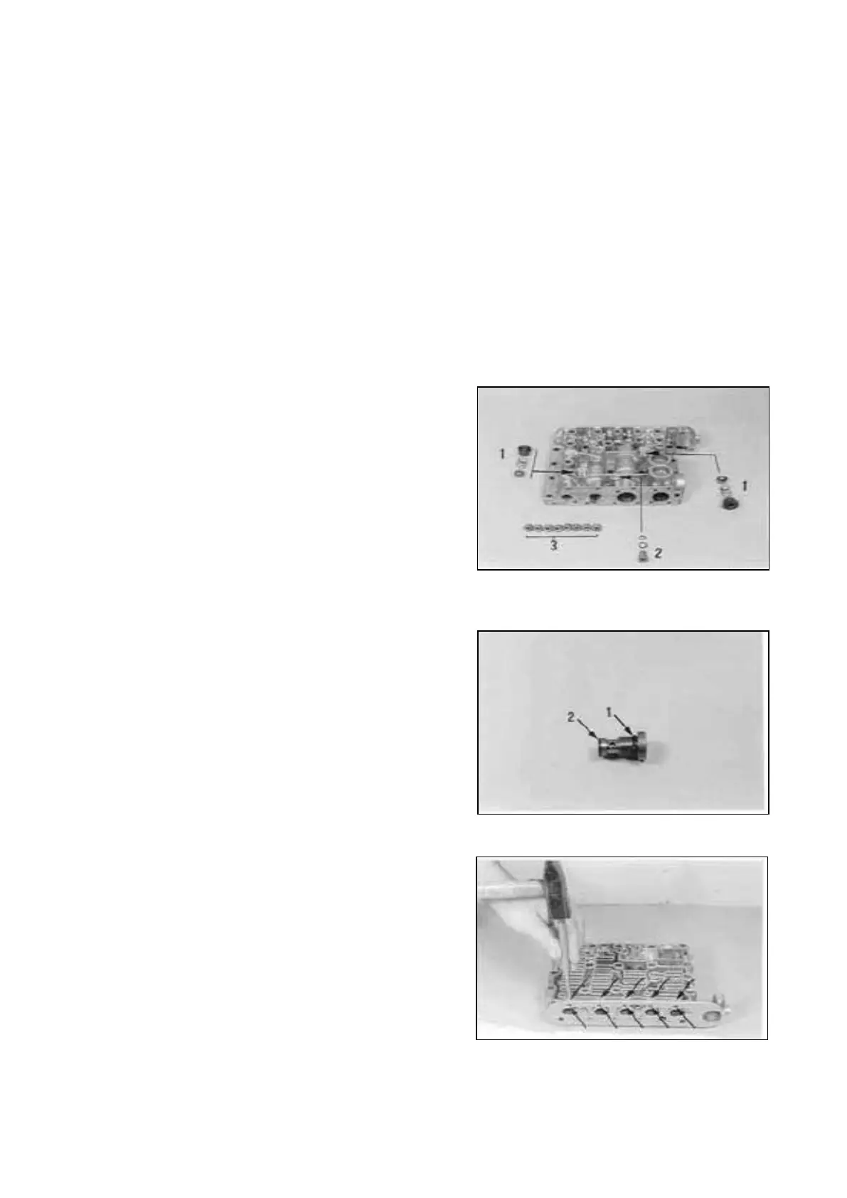
Ref. Figure 170 : 1 = Check valve (2x)
2 = Diaphragm
3 = Screw plugs
Install components according to the Illustration on
the right.
NOTE ;
Employ new O-Rings for all screw plugs.
Figure 171 shows the positions of the O-Rings on
the diaphragm 2.
(Fasten O-Ring 6 x 1,5 mm/Arrow 2 with grease) !
Δ t l is determined by the diaphragm 2
(pay attention to Notes, Page 12 ... 14) !
Torque limit :
Screw plug M10x 1 20 Nm
Screw plug Ml8x1,5 35 Nm
Diaphragm 20 Nm
Close the bores by means of balls (10 pieces Ø
4,50 mm).
Transmission and Torque Converter SPC000007
Page 67