3.2.1.3 Inductive transmitter
Adjust required gap 0,50 mm between the contact
area/inductive transmitter and the spur gear (tooth
tip).
Figure 286 to Example "N".
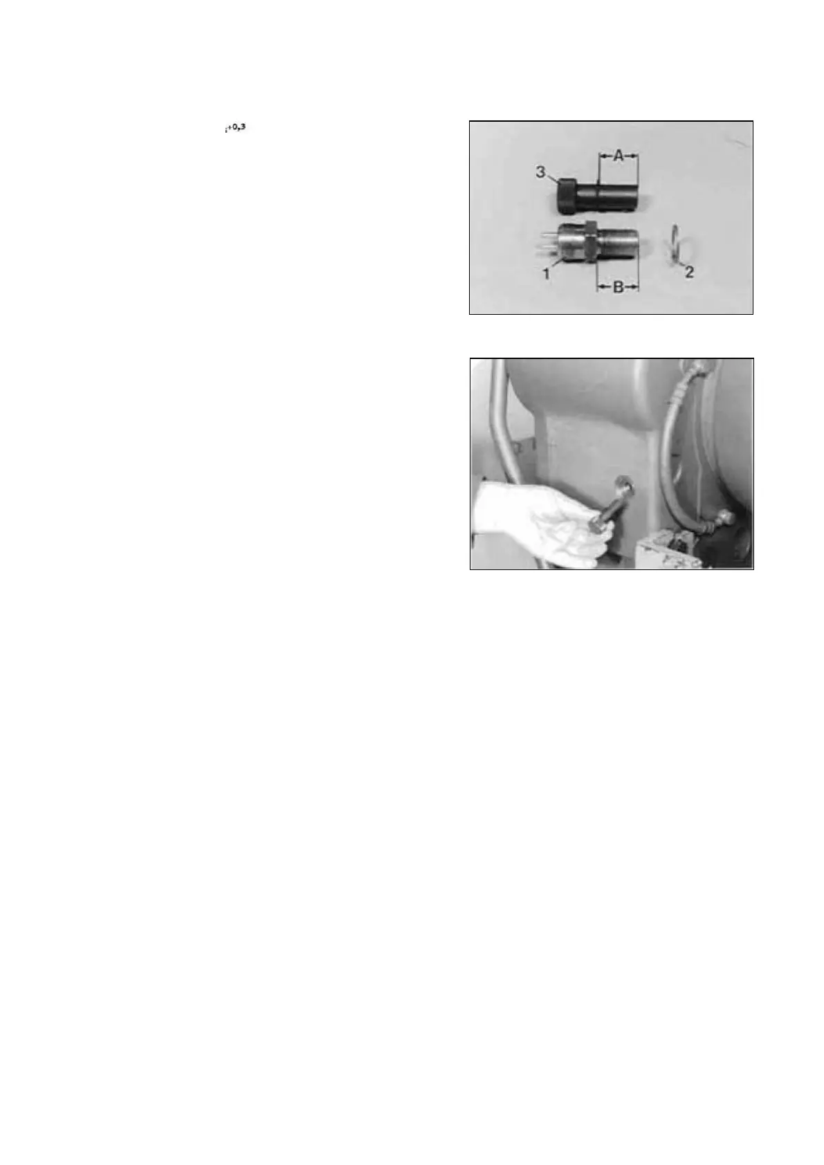
Ref. Figure 286 ; 1 = Inductive transmitter
2 = Shim
3 = Measuring pin( S )
Measuring pin ( S ) 5870 200 040
Insert measuring pin until the end face has got
contact on the tooth tip of the spur gear as well as
the circlip is located on the screwin surface of the
housing.
NOTE ;
The tooth tip must be centrically located to the
housing bore, if necessary, align the spur gear
accordingly !
Remove measuring pin and measure Dimension "A"
from the end face/measuring pin to the circlip (see
Figure 286).
Dimension ―A‖ e.g. 26,00 mm
Determine Dimension "B" from the contact
surface/inductive transmitter to the contact area
(see Figure 286).
Dimension "B‖ e.g. 27,10 mm
Example "N‖ :
Dimension "A‖ 26,00 mm
required gap e.g. - 0,60 mm
Difference = Adjustment dimension 25,40 mm
Dimension "B‖ 27,10 mm
Adjustment dimension - 25,40 mm
Difference = Shim(s) e.g. 1,70 mm
Assemble corresponding shim and install the
inductive transmitter.
NOTE :
Wet thread of inductive transmitter with sealing
compound !
Transmission and Torque Converter SPC000007
Page 165
 Loading...