Initial Setup & Basic Operations DTG M Series Maintenance Manual
3.6.8 Bi-Directional (Bi-D) Adjustment
This menu option is used to align the head positions for Bi-Directional printing – that is, to align
the print position of each nozzle between the left (CCW) direction print pass of the print head and
the right (CW) direction print pass of the print head. This adjustment may be necessary if printed
output, particularly fine lines, are blurry or appear as double lines.
Blurry prints or double lines may also result if the media height has not been set correctly. Ensure
that the media height is correctly set 3.6.5 "Checking media height" p.51
3.6.8.1 Overview of Bi-D Adjustment
To align the head position for Bi-Directional printing, there are two basic (repeatable) steps : 1. The
adjustment process will first print out a Bi-D test print pattern, from which it will be necessary to
identify the difference between the CW printing position and the CCW printing position. 2. Enter
the revised parameter to move the CW and CCW printing positions. The Bi-D test print pattern will
print again, and the parameter can be further revised if necessary.
Due to the print head characteristics, only one adjustment value is used for all nozzle rows.
Therefore, adjust the parameter value so that the position of all the nozzle rows are aligned on
average.
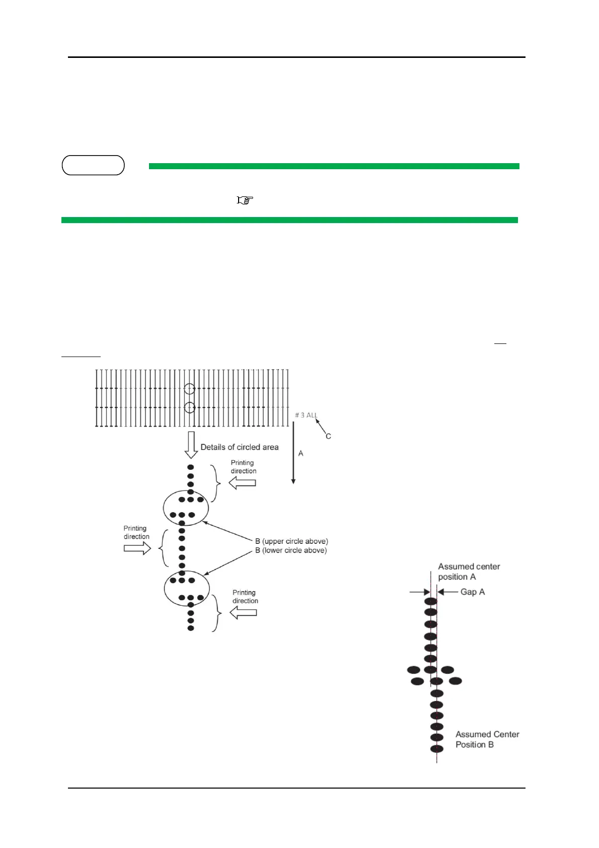
A. Media feed direction
B. Adjust the setting value so that
the printed dots are aligned at this
connecting point.
C. Indicates the adjustment pattern
printed - # 3 = Bi-D High1, # 4 = Bi-
D High2
Make an adjustment so that the size of the
gap A is smaller than the half size of the dot.
3-9 PRINTED BI-D TEST PATTERN
3-10 DESIRED NOZZLE ALIGNMENT