To reach the fuse boxes, remove the
cover as described in chapter
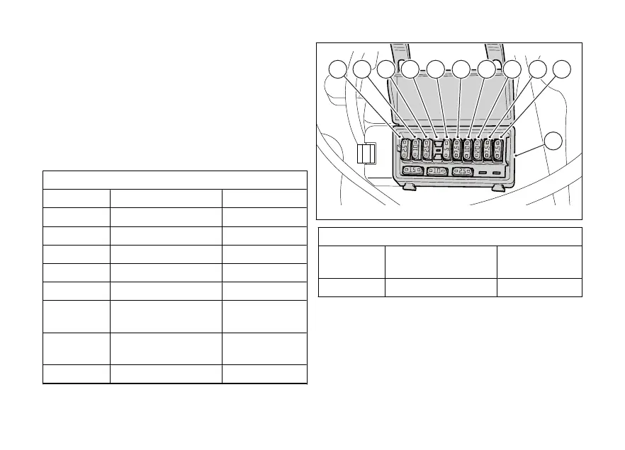
“Charging the To expose the fuses used in
box (A), remove the box protection lid. Mounting
position and ampere capacity are marked on it. Three
spare fuses (10 A, 15 A and 25 A) are positioned at the
side.
Refer to the table below to identify the circuits
protected by the fuses in box (A) and their ratings.
Fuse box (A) key
Pos. El. item Rat.
1 EMS LOAD RELAY 25 A
2 FUEL PUMP RELAY 10 A
3 DASHBOARD 25 A
4 - -
5 KEY1 EMS/ABS/IMU 5 A
6 KEY2 DASH/BBS/
SMEC
7.5 A
7 KEY5 ACCESSO‐
RIES/SW
10 A
8 IGN. RELAY 20 A
Fuse box (A) key
9 DIAGNOSTIC/
RECHARGE
7.5 A
10 STARTER RELAY 7.5 A
Fig 266
313