1-7
Chapter 1 Prior to Use
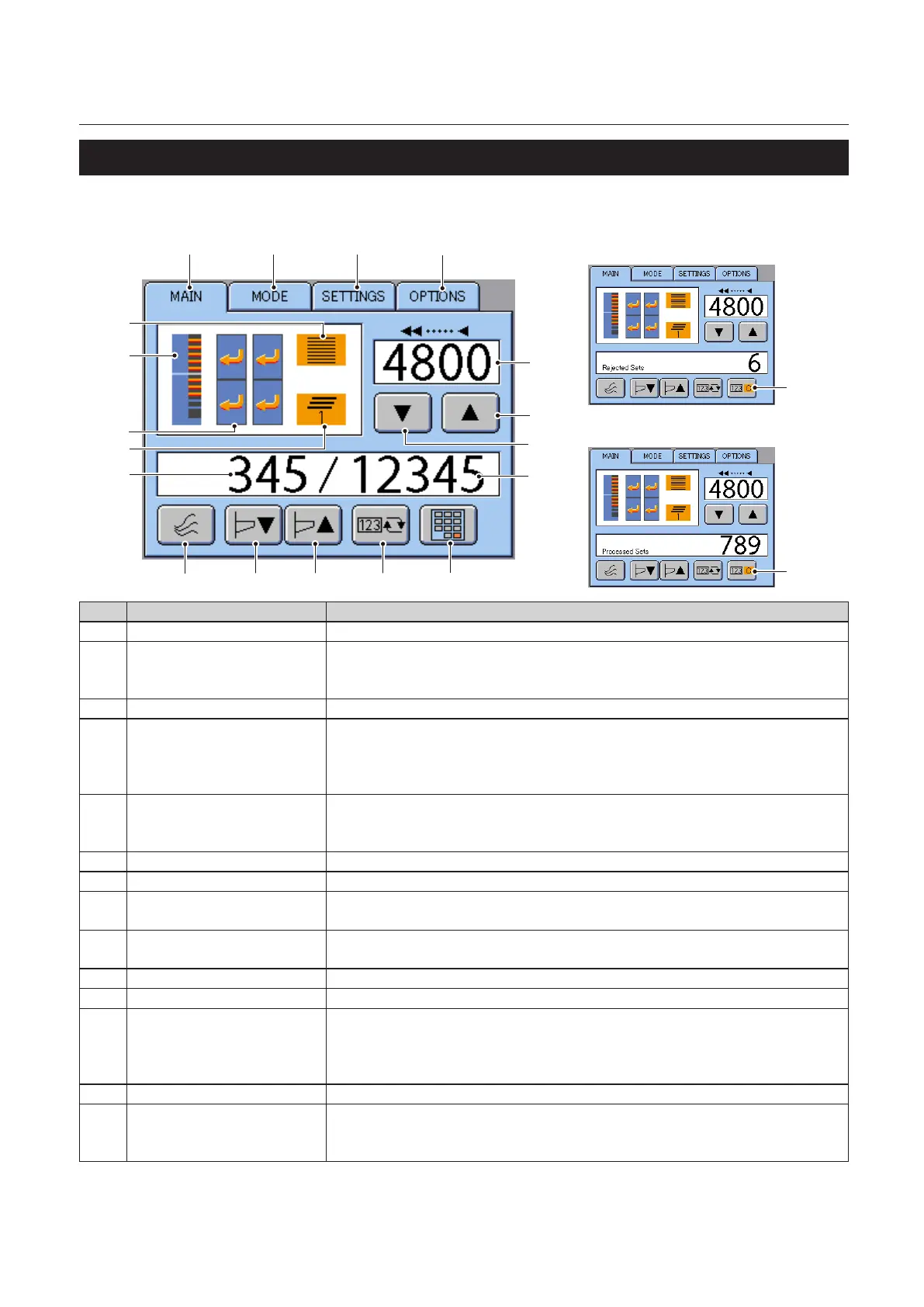
5-2. Touch Panel
MAIN Menu
[1]
[2] [3]
[4]
[10]
[5]
[6]
[7]
[8]
[14]
[15]
[19]
[19]
[16][17][18]
[9]
[13]
[12]
[11]
<No. of rejects display area>
<Total no. of sets display area>
No. Name Function
[1] Main Tab Displays the main menu.
[2] MODE Tab Displays the mode screen.
When two DSC-10/20s are connected (one is called tower A and the other tower
B in this manual), this mode screen will only be displayed on tower A.
[3] SETTINGS Tab Displays the Setup screen.
[4] OPTIONS Tab Displays the Optional Settings screen.
Displayed when LUL-HM or the ejection stacker is connected.
When two DSC-10/20s are connected (one is called tower A and the other tower
B in this manual), this mode screen will only be displayed on tower A.
[5] Processing Speed Display Displays the processing speed in number of sets/time.
If “0” is displayed while the touch panel backlight is o, it means that presetting
is required.
[6] Processing Speed-Up Key Increases the processing speed.
[7] Processing Speed-Down Key Decreases the processing speed.
[8] No. of Sets Entered Display
Area
Displays the value entered with the no. of sets entry key.
[9] No. of Processing Sets Displays the number of sets already processed (counted up) or the number of
sets left to be processed (counted down) from the number of sets entered.
[10] Program Mode This displays the currently selected program mode.
[11] Preset Data Bins that have been preset and are loaded with paper are displayed in orange.
[12] Tower Information Displays the connected states of the towers (A and B), paper ejection direction,
and processing block information.
When the block mode is set to 1/2 or 1/4, touch to change the block starting
operations rst.
[13] Overlap Amount Displays the paper overlap amount of the collated sets.
[14] No. of Sets Entry Key Switches to the No. of processing sets entry menu.
When two DSC-10/20s are connected (one will be called tower A and the other
tower B in this manual), this mode screen will only be displayed on tower A.
 Loading...


