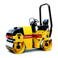
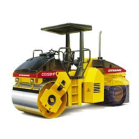
Machine description
4812161201_F.pdf2018-04-17
Function description
No Designation Symbol FunctionNo Designation Symbol Function
1. Starter switch Positions 1-2: Shut off position, key can be removed.1. Starter switch Positions 1-2: Shut off position, key can be removed.
Position 3a: All instruments and electric controls are supplied with
power.
Position 3a: All instruments and electric controls are supplied with
power.
Position 3b: Glowing. Hold the starter switch in this position until
the lamp goes out. The starter motor is activated in the next
position.
Position 3b: Glowing. Hold the starter switch in this position until
the lamp goes out. The starter motor is activated in the next
position.
Position 3c: Starter motor activation.Position 3c: Starter motor activation.
2. Throttle control
In forward position, the engine idles.
In backward position, the engine runs at full speed.
2. Throttle control
In forward position, the engine idles.
In backward position, the engine runs at full speed.
3. Emergency stop When pressed, the emergency stop is activated. The engine
switches off and the brakes are activated. Brace yourself for a
sudden stop.
3. Emergency stop When pressed, the emergency stop is activated. The engine
switches off and the brakes are activated. Brace yourself for a
sudden stop.
4. Vibration On/Off. Switch Press once and release to switch vibration on. Press again to
switch the vibration off.
4. Vibration On/Off. Switch Press once and release to switch vibration on. Press again to
switch the vibration off.
5. Handbook compartment Pull up and open the top of the compartment for access to
handbooks.
5. Handbook compartment Pull up and open the top of the compartment for access to
handbooks.
6. Forward/Reverse lever The engine can only be started when the lever is in neutral. The
engine will not start if the forward/reverse lever is not in the
neutral position.
Direction of travel and speed of the roller is regulated with the
forward/reverse lever. Move the lever forward to drive the roller
forwards, etc.
The speed of the roller is proportional to the distance of the lever
from the neutral position. The further the lever is from the neutral
position, the higher the speed.
7. Seat switch Remain seated at all times when operating the roller. If the
operator stands up during operation, a buzzer sounds. After 4
seconds the brakes are activated and the engine stops.
7. Seat switch Remain seated at all times when operating the roller. If the
operator stands up during operation, a buzzer sounds. After 4
seconds the brakes are activated and the engine stops.
8. Fuse box (on control
column)
Contains fuses for the electrical system. See under the heading
‘Electrical system’ for a description of fuse functions.
8. Fuse box (on control
column)
Contains fuses for the electrical system. See under the heading
‘Electrical system’ for a description of fuse functions.
9. Instrument cover Lowered over the instrument plate to protect the instruments from
the weather and sabotage. Lockable
9. Instrument cover Lowered over the instrument plate to protect the instruments from
the weather and sabotage. Lockable
12. Sprinkler, switch Upper position = switching on of flow of water to drum.
Intermediate position = Sprinkling switched off
Lower position = switching on of water to drum via
forward/reverse lever. The flow of water can be controlled by
means of the sprinkler timer (13).
12. Sprinkler, switch Upper position = switching on of flow of water to drum.
Intermediate position = Sprinkling switched off
Lower position = switching on of water to drum via
forward/reverse lever. The flow of water can be controlled by
means of the sprinkler timer (13).
13. Sprinkler timer (Optional) Variable adjustment of water flow from 0-100%. Only works when
AUTO (12) is pressed in.
13. Sprinkler timer (Optional) Variable adjustment of water flow from 0-100%. Only works when
AUTO (12) is pressed in.
14. Driving lights, switch
(Optional)
Upper position = Traffic lighting goes on
Intermediate position = Lighting switched off
Lower position = Parking light goes on
14. Driving lights, switch
(Optional)
Upper position = Traffic lighting goes on
Intermediate position = Lighting switched off
Lower position = Parking light goes on
31