iv
Copyright © 2022 Eaton Corporation plc. All rights reserved.
List of Figures
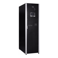
Figure 2-1: Eaton 93PR UPS ................................................................................................................................................. 6
Figure 2-2: Structure of 15-40k product ................................................................................................................................. 7
Figure 2-3: Structure of 60-80k product.................................................................................................................................. 8
Figure 2-4: 93PR UPS Wiring Diagram .................................................................................................................................. 9
Figure 2-5: Route of the electric energy running through the UPS in Online mode ..............................................................11
Figure 2-6: Route of the electric energy running through the UPS in ESS mode ................................................................ 12
Figure 2-7: Route of the electric energy running through the UPS in battery mode ............................................................. 13
Figure 2-8: Route of the electric energy running through the UPS in bypass mode ............................................................ 14
Figure 3-1: Clearance for the UPS cabinet........................................................................................................................... 20
Figure 3-2: UPS dimensions (15–40k) ............................................................................................................................... 21
Figure 3-3: UPS dimensions (60–80k) ................................................................................................................................. 22
Figure 4-1: 15–40k unpacking diagram ................................................................................................................................ 31
Figure 4-2: 60–80k unpacking diagram ................................................................................................................................ 32
Figure 4-3: Gland Plate and Connector Locations .............................................................................................................. 34
Figure 4-4: Locations of cover plate and connecting terminals (60–80k) ............................................................................. 35
Figure 4-5: Schematic diagram of the parallel UPS system ................................................................................................ 39
Figure 4-6: Simplied wiring of CAN and Pull-Chain of the parallel UPS system................................................................. 40
Figure 5-1: Communication Interfaces ................................................................................................................................ 41
Figure 5-2: Gigabit Network Card ......................................................................................................................................... 43
Figure 5-3: Second-generation Environmental Monitoring Probe ........................................................................................ 43
Figure 5-4: Industrial Gateway Card..................................................................................................................................... 44
Figure 5-5: Standard AS400/RS232 card ............................................................................................................................. 44
Figure 6-1: UPS Controls and Indicators .............................................................................................................................. 47
Figure 6-2: Components of the touch screen (Home interface) .......................................................................................... 49
Figure 6-3: Menu interface ................................................................................................................................................... 50
Figure 6-4: Input interface .................................................................................................................................................... 51
Figure 6-5: Output interface.................................................................................................................................................. 51
Figure 6-6: Bypass interface................................................................................................................................................. 51
Figure 6-7: Battery interface ................................................................................................................................................. 52
Figure 6-8: Password verication interface .......................................................................................................................... 52
Figure 6-9: System interface ............................................................................................................................................... 53
Figure 6-10: Switch to bypass interface ............................................................................................................................... 53
Figure 6-11: Conrmation interface ...................................................................................................................................... 54
Figure 6-12: UPS interface .................................................................................................................................................. 54
Figure 6-13: UPM interface .................................................................................................................................................. 55
Figure 6-14: UPM shutdown interface .................................................................................................................................. 55
Figure 6-15: Active Log interface .......................................................................................................................................... 56
Figure 6-16: History Log interface ........................................................................................................................................ 56
Figure 6-17: Clear Log interface ........................................................................................................................................... 56
Figure 6-18: Info. interface 1 ................................................................................................................................................ 57
Figure 6-19: Info. interface 2 ................................................................................................................................................ 57
Figure 6-20: Password verication setting interface ............................................................................................................. 58
Figure 6-21: Setting interface .............................................................................................................................................. 58

 Loading...