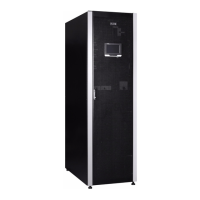
Eaton 93PR 15-80 kW UPS
Installation and Operation Manual
v
Copyright © 2022 Eaton Corporation plc. All rights reserved.
Figure 6-22: Setting - General interface ............................................................................................................................... 59
Figure 6-23: Setting - General - Time interface ................................................................................................................... 59
Figure 6-24: Setting - Output interface ................................................................................................................................. 60
Figure 6-25: Setting - Meters interface ................................................................................................................................. 60
Figure 6-26: Setting - Password interface ........................................................................................................................... 60
Figure 6-27: Control password modication interface .......................................................................................................... 61
Figure 6-28: Control password modication interface ......................................................................................................... 61
Figure 6-29: Control password modication interface ......................................................................................................... 62
Figure 6-30: Control password modication interface .......................................................................................................... 62
Figure 6-31: Setting password modication interface.......................................................................................................... 63
Figure 6-32: Service maintenance reminder interface.......................................................................................................... 63
Figure 6-33: Service maintenance reminder setting interface ............................................................................................. 64
Figure 6-34: Location of service reminder function ............................................................................................................. 64
Figure 6-35: Service reminder settings page........................................................................................................................ 65
Figure 6-36: Fan replacement reminder settings................................................................................................................. 65
Figure 6-37: Switch status in online mode............................................................................................................................ 72
Figure 6-38: Switch status in maintenance bypass mode .................................................................................................... 72
Figure 6-39: Switch status in Maintenance Bypass Mode .................................................................................................... 73
Figure 6-40: Switch status in online mode............................................................................................................................ 73
Figure 7-1: Location of 15–40k air lter screen .................................................................................................................... 76
Figure 7-2: Location of 60–80k air lter screen .................................................................................................................... 76

 Loading...