8 SmartWire-DT
8.9 Programming
DS7 Soft starter 09/16 MN03901001Z-EN www.eaton.com 153
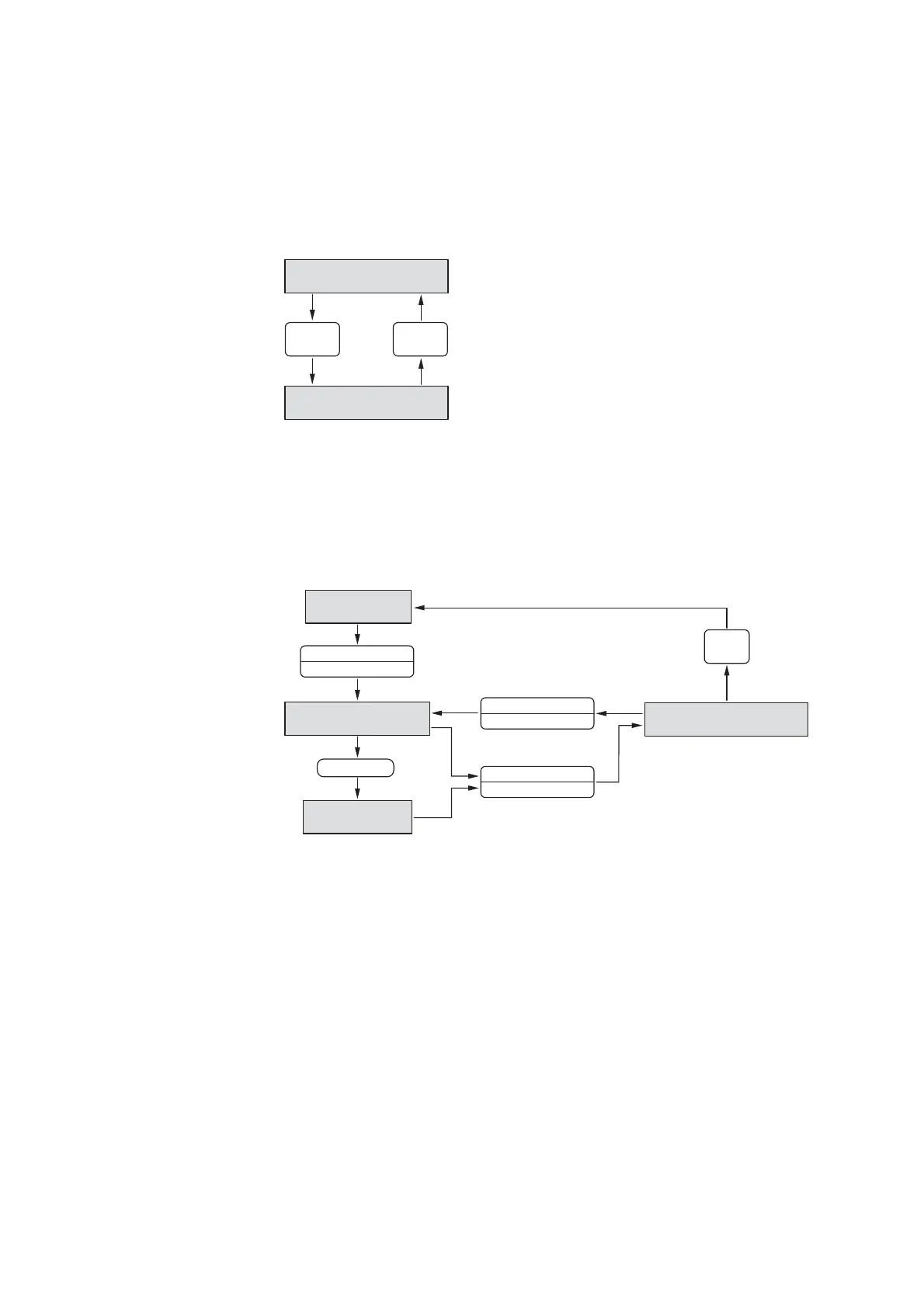
8.9.2.6 Network – State diagram for profiles 4, 5, 6, 10
If profile 4, 5, 6, or 10 (Short) is used with PNU 928.0 = 1, the state diagram
shown below will apply.
Figure 119: State diagram: Network (profiles 4, 5, 6, 10)
8.9.2.7 Network – S4: Operation, profiles 4, 5, 6, 10
If profile 4, 5, 6, or 10 (Short) is used with PNU 928.0 = 1, the state diagram
shown below will apply. The transitions will take place when the state of the
EN_Set bit is changed.
Figure 120: State diagram: Network – S4 (profiles 4, 5, 6, 10)
S3: Switched On
Bit 2 = 1
S4: Operation
Bit 2 = 1
Bit 2 = 0
(EN_Op)
Bit 2 = 1
(EN_Op)
S4.1: Idle Operation
Bit 3 = 0; Bit 4 = 0
S4.2 Ramping Up Operation
Bit 3 = 1; Bit 4 = 0
S4.3: Ramping Down Operation
Bit 3 = 1; Bit 4 = 0
S4.4: TOR Operation
Bit 3 = 1; Bit 4 = 1
Bottom
of Ramp
Ramp Down
Bit 0 = 0 (EN_Set)
Ramp Up
Bit 0 = 1 (EN_Set)
Top of Ramp
Ramp Up
Bit 0 = 1 (EN_Set)

 Loading...