97
13.4.16 Write Multiple Registers – Function 16 – Response
Register Address
Number of coils that have been written
Quantity
This represents the number of registers the user wishes to be written
Typical Example of Message Format
To write channel 10 abnormal on a 20 way annunciator at node 1 the user would need to send
the following message
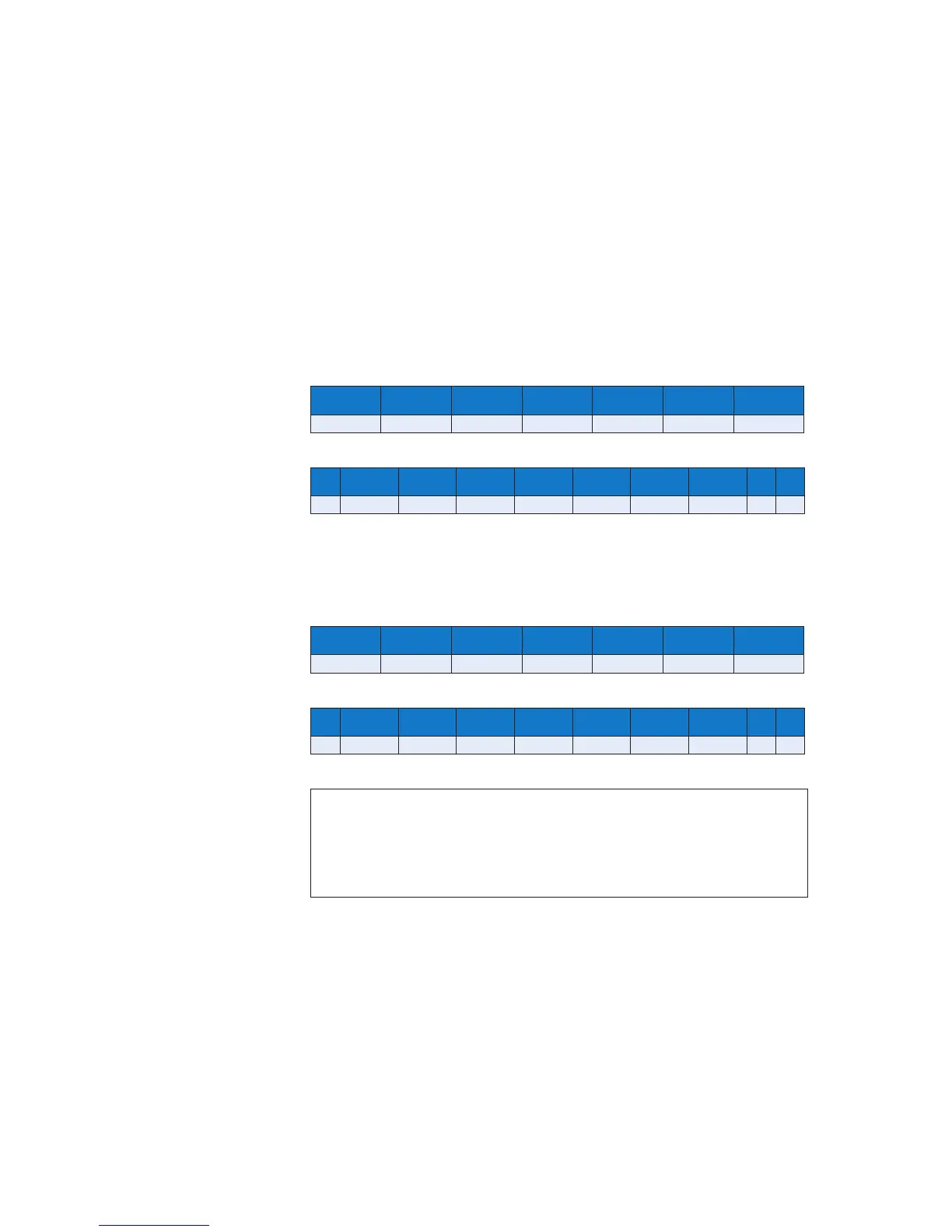
RTU
ADDRESS FUNCTION REGISTER
ADDRESS
No. of
Registers
BYTE COUNT DATA ERROR
CHECK
01 10 00 0A 00 01 02 00 01 67 3A
ASCII
: ADDRESS FUNCTION REGISTER
ADDRESS
No. of
Registers
BYTE
COUNT
DATA ERROR
CHECK
CR LF
3A 30 31 31 30 30 30 30 41 30 30 30 31 30 32 30 30 30 31 45 31 0D 0A
To write Reset group 1 PB to the abnormal state on an annuciator at node
2 in the system you would need to send the following message
RTU
ADDRESS FUNCTION REGISTER
ADDRESS
No. of
Registers
BYTE COUNT DATA ERROR
CHECK
02 10 01 02 00 01 02 00 01 62 42
ASCII
: ADDRESS FUNCTION REGISTER
ADDRESS
No. of
Registers
BYTE
COUNT
DATA ERROR
CHECK
CR LF
3A 30 32 31 30 30 31 30 32 30 30 30 31 30 32 30 30 30 31 45 37 0D 0A
NOTE
On systems supplied before 30st July 2010 the input status is OR’d with the actual
contact state. If the input is serial only please ensure the contact type is set to Normally
Open and no customer wiring is made to the customer terminals located on the rear of
the associated cell.
With serial inputs 0 = Input Normal and 1 = Input Abnormal