47
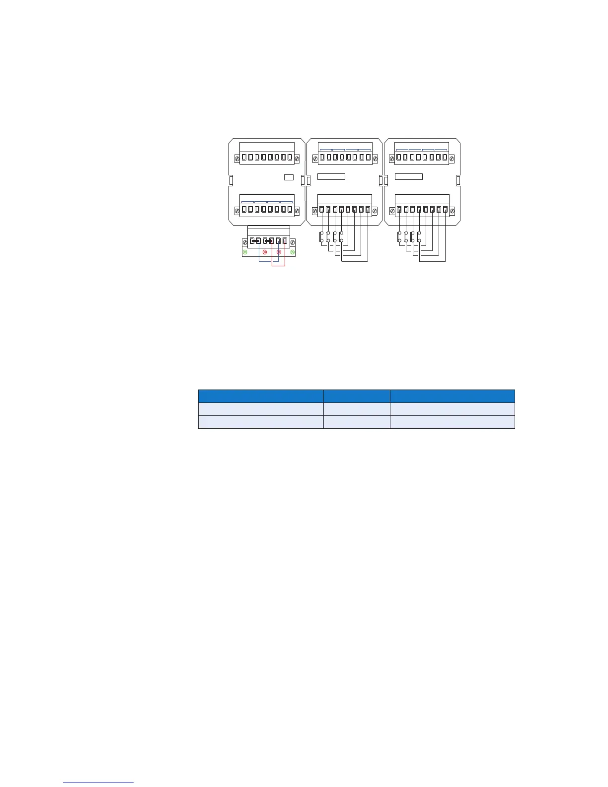
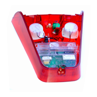
5.5 Standard 24VDC Signal Input Wiring
Each channel on the alarm card is provided with a 3 pin header and 2 way shorting bar which
allows the user to select the inputs to operate on 24V
On standard RTK 725B systems the 24VDC logic supply is factory linked to the signal supply
input terminals as follows:-
Logic Supply Signal Supply
OV To OVC
+V To +VC
This provides a +24VDC signal contact supply on all C terminals as shown above.
LED F2 is used to indicate that the signal supply, (+VC), fuse has blown.
As all *C terminals are internally linked the customer can connect each input contact to a
dedicated terminal as shown in the middle cell or a single feed can be used for multiple
contacts as shown in the right hand cell.
The common return for all remote pushbuttons is +V (+24VDC)
To set the signal supply voltage on each input to 24VDC a drop-down menu is provided in the
Configuration Software. Selection is made under the Input tab using the drop-down menu
labelled “Field Contact Voltage (V)”
WRP
OV OV +V+V OVC +VC
Rx
F1 F2
Tx
CHANNEL
21
5 - 8
3C
INPUTS
4
3
1C 2C
AR
4C
AR
INPUTS
CHANNEL
3
1 2 1C4
1 - 4
CR1 CR2
CR3
CR4
24VDC SIGNAL SUPPLY
LINKED FROM THE
LOGIC SUPPLY
2C
3C
4C
-- R2R1
R3
R4
R1
R3
R2 R4P1 P2
P3
P4
P5 P6