13.4 Protocols
13.4.1 MODBUS
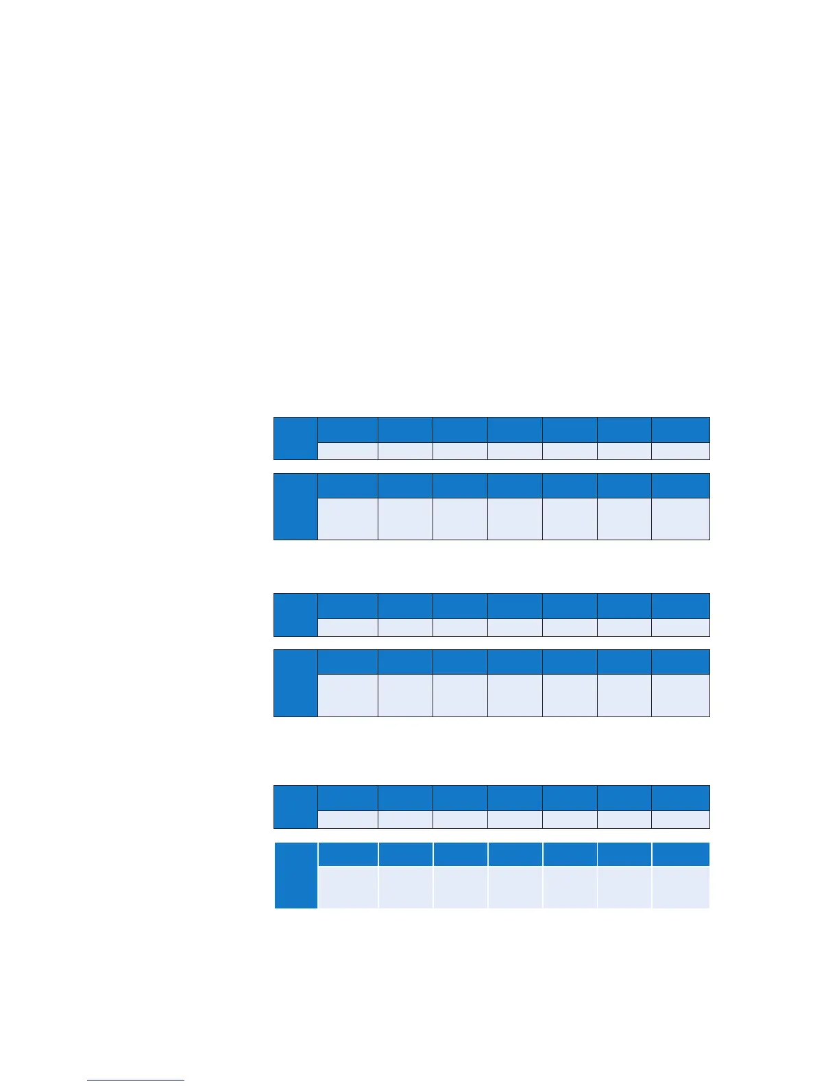
The tables below show the standard message formats for data interchange, for both ASCII
(standard comm’s version Only) and RTU protocols.
ASCII tables Each character represents 7 bit binary data in ASCII format with the exception
of the characters in brackets, which should be considered as one character.
X represents a character with more than one possible value.
All characters are framed with 1 start bit, 1 parity bit and 1 stop bit.
RTU tables. Each character represents 8 bit binary data in hexadecimal format.
Y represents a character with more than one possible value.
All characters are framed with 1 start bit, 1 parity bit and 1 stop bit.
Read Request – Master
ASCII
START ADDRESS FUNCTION REGISTER
ADDRESS
NO OF
REGISTERS
ERROR
CHECK
STOP
: XX XX XXXX XXXX XX [LF] [CR]
RTU
START ADDRESS FUNCTION REGISTER
ADDRESS
NO OF
REGISTERS
ERROR
CHECK
STOP
ELAPSED TIME
3 ½
CHARACTERS
MIN
Y Y YY YY YY
ELAPSED TIME
3 ½
CHARACTERS
MIN
Read Request – Slave
ASCII
START ADDRESS FUNCTION BYTE
COUNT
DATA ERROR
CHECK
STOP
: XX XX XX XX XX [LF] [CR]
RTU
START ADDRESS FUNCTION BYTE
COUNT
DATA ERROR
CHECK
STOP
ELAPSED TIME
3 ½
CHARACTERS
MIN
Y Y Y YY YY
ELAPSED TIME
3 ½
CHARACTERS
MIN
Single Write Request/Response
Master write request and slave write response, are the same.
ASCII
START ADDRESS FUNCTION REGISTER
ADDRESS
DATA ERROR
CHECK
STOP
: XX XX XXXX XXXX XX [LF] [CR]
RTU
START ADDRESS FUNCTION REGISTER
ADDRESS
DATA ERROR
CHECK
STOP
ELAPSED TIME
3 ½
CHARACTERS
MIN
Y Y YY YY YY
ELAPSED TIME
3 ½
CHARACTERS
MIN