13.4.2 Modbus Slave – Entry Level
Function Descriptions
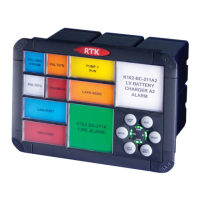
This section describes the process of reading from and writing data to a RTK 725B slave
annunciator
Read Coil Status – Function 01 – Request
Register Address
This is used to address the “start” channel to be read for example the first channel in the
system “channel 1” would be register address 00 00
To read the input read coils 0-3
To read the remote pushbutton inputs on the card read coils 4-6
Number of Registers
This represents the number of coils, (Inputs), the user wishes to read. This can be 1-7 coils.
13.4.3 Read Coil Status – Function 01 – Response
Byte Count
This represents the number of bytes sent
Data
This represents the status of the requested channel
Input
0 = Input Normal
1 = Input Abnormal
Typical Example of Message Format
To read all of the inputs available on the first alarm card in the system the user would need to
read 4 digital and 3 remote pushbutton inputs using the following message format
ADDRESS FUNCTION REGISTER ADDRESS No. of REGISTERS ERROR CHECK
01 01 00 00 00 07 7D C8
To read channel two on the second alarm card in the system you would need the following
message format
ADDRESS FUNCTION REGISTER ADDRESS No. of REGISTERS ERROR CHECK
02 01 00 01 00 01 AC 39