3 LOGIC SUPPLY & FUSING
All RTK 725B Alarm Annunciators operate from a 24VDC logic supply.
Any external power supply connected to the annunciator must be compliant to UL60950 or
EN60950 or suitable equivalent standards.
3.1 Externally Powered Systems
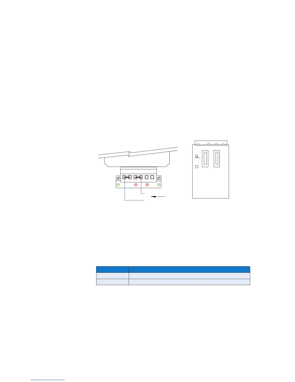
When external power supplies are used 24VDC must be connected to terminals OV and +V as
shown below.
Fuse F1, (5 x 20mm 5A), is provided on the underside of the power input card to protect the
alarm logic and +24VDC is internally linked to all of the associated cards within the system.
Red LED F1 is used to indicate that the +V fuse has blown.
Fuses
FU-1A-002 - 5 x 20mm 1A signal supply fuse
FU-5A-003 - 5 x 20mm 5A logic supply fuse
3.2 SI/O Card Versions
Part No Description
CB6648POP1 Used on standard versions with remote power supplies
CB6648POP3 Used on versions with RS485 communications & remote power supplies
REAR VIEW
OV OV +V+V 0VC +VC
Rx
F1 F2
Tx
FROM EXTERNAL
24VDC SUPPLY
(+)
(OV)
F1
UNDERSIDE VIEW OF
POWER INPUT CARD
F2
5A / T
1A / F
1A / F
LOGIC
SUPPLY
FUSE
SIGNAL
SUPPLY
FUSE