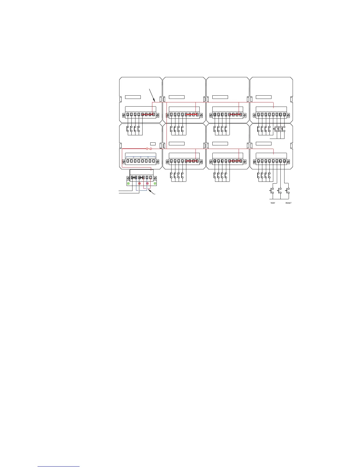
7.8 Typical Small Window Version,
(each alarm window = 30mm w x 30mm h),
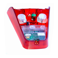
The above rear view shows a typical small window RTK 725B configured 4 cells wide x 2 cells
high with twenty eight active alarms, common relay card and an integral pushbutton module.
Each cell within the Annunciator is used to display four alarm channels.
In the example above cell 0 and cell 1 are equipped with a four channel alarm card plus
provision for three remote pushbutton inputs. As standard the pushbutton inputs are software
configured as follows:-
Cell 0 ---- P1 = Lamp Test / P2 = Ack / P3 = Reset
Cell 1 ---- P1 = System Test / P2 = Silence / P3 = 1st Reset
These can be reconfigured in software as required.
In small window versions of the RTK 725B each cell is supplied with an alarm card and the
outputs are distributed to four channels within the cell.
WR
OV OV +V+V OVC +VC
Rx
F1 F2
Tx
CR1 CR2 CR3 CR4
F2 - 1A
24VDC LOGIC
SUPPLY VOLTAGE
INTERNAL SIGNAL
SUPPLY COMMON
CHANNEL
AP
P1
EXT. PB
INPUTS
2
3
1
4 C
P3
P2
1 - 4
2C
INPUTS
2
3
1
1C4
4C3C
A
17 - 20
CHANNEL
1 2
4C1C4
3
3C2C
INPUTS
A
CHANNEL
9 - 12
1 2 4C1C4
3
3C2C
INPUTS
A
CHANNEL
25 - 28
3
21 4 1C 2C
3C
4C
INPUTS
A
CHANNEL
21 - 24
1 2 4C
INPUTS
1C4
3
3C
2C
CHANNEL
13 - 16
A
1
INPUTS
3
42
5 - 8
CHANNEL
AP
24VDC SIGNAL
SUPPLY VOLTAGE
CELL 6 CELL 4 CELL 2 CELL 0
CELL 7 CELL 5 CELL 3 CELL 1
+V
+V
P3
P2P1
C
EXT. PB
SYSTEM
MUTE
1ST