53
5.11 Optional 48VAC Signal Input Wiring
NOTE:
In applications that require 48VAC signal inputs we supply optional 4 channel alarm
cards in place of the standard version
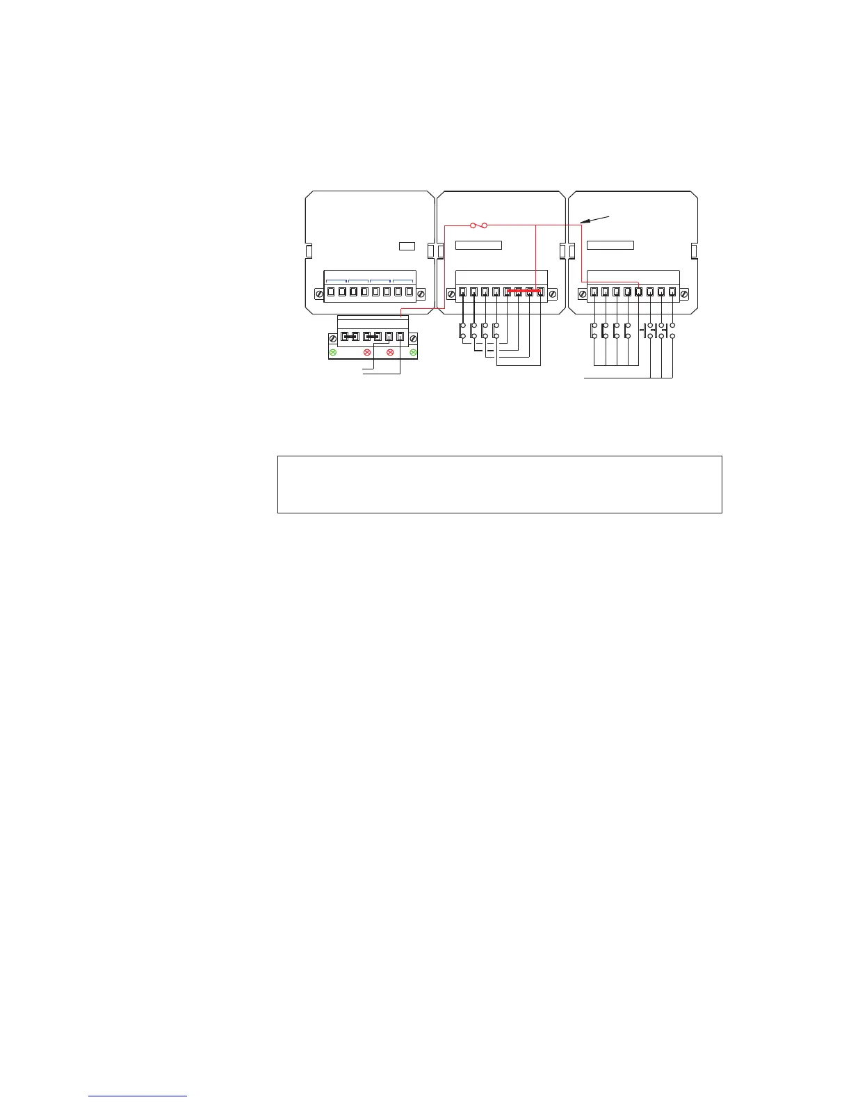
48VAC Signal Supply
On RTK 725B systems where 48VAC is required as a signal supply voltage this needs to be
derived externally and connected to terminals OVC and +VC as typically shown above.
IMPORTANT:- Please ensure there are no external links between the logic supply and the signal
supply input terminals i.e. OV and OVC and +V and +VC before applying the high voltage signal
supply
LED F2 is used to indicate that the signal supply fuse has blown.
Fuse F2, (5 X 20mm 1A), is provided on the power input card to protect the signal supply
voltage and the 48VAC is internally linked to all of the associated input card *C terminals to
allow distribution to the external field contacts.
As all *C terminals are internally linked the customer can connect each input contact to a
dedicated terminal as shown in the middle cell or a single feed can be used for multiple
contacts as shown in the right hand cell.
The common return for all remote pushbuttons is +V (+24VDC)
To set the signal supply voltage on each input to 48VAC a drop-down menu is provided in the
Configuration Software. Selection is made under the Input tab using the drop-down menu
labelled “Field Contact Voltage (V)”
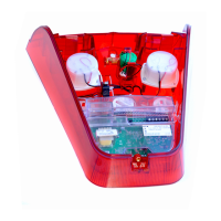
WR
725B SMALL WINDOW VERSION TYPICAL REAR VIEW
OV OV +V+V OVC +VC
Rx
F1 F2
Tx
CHANNEL
21
5 - 8
3C
INPUTS
4
3
1C 2C
A
4C
AP
INPUTS
CHANNEL
3
1 2
1C4
1 - 4
P3
P1 P2
CR1 CR2 CR3 CR4
F2 - 1A
SUPPLY VOLTAGE
EXT PB
INTERNAL SIGNAL
SUPPLY COMMON
CELL 2 CELL 1 CELL 0
+V
48VAC SIGNAL