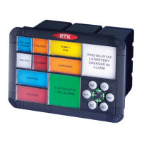
45
5 SIGNAL VOLTAGE SETTING / WIRING
5.1 Setting Inputs for use with 24VDC or 125VDC
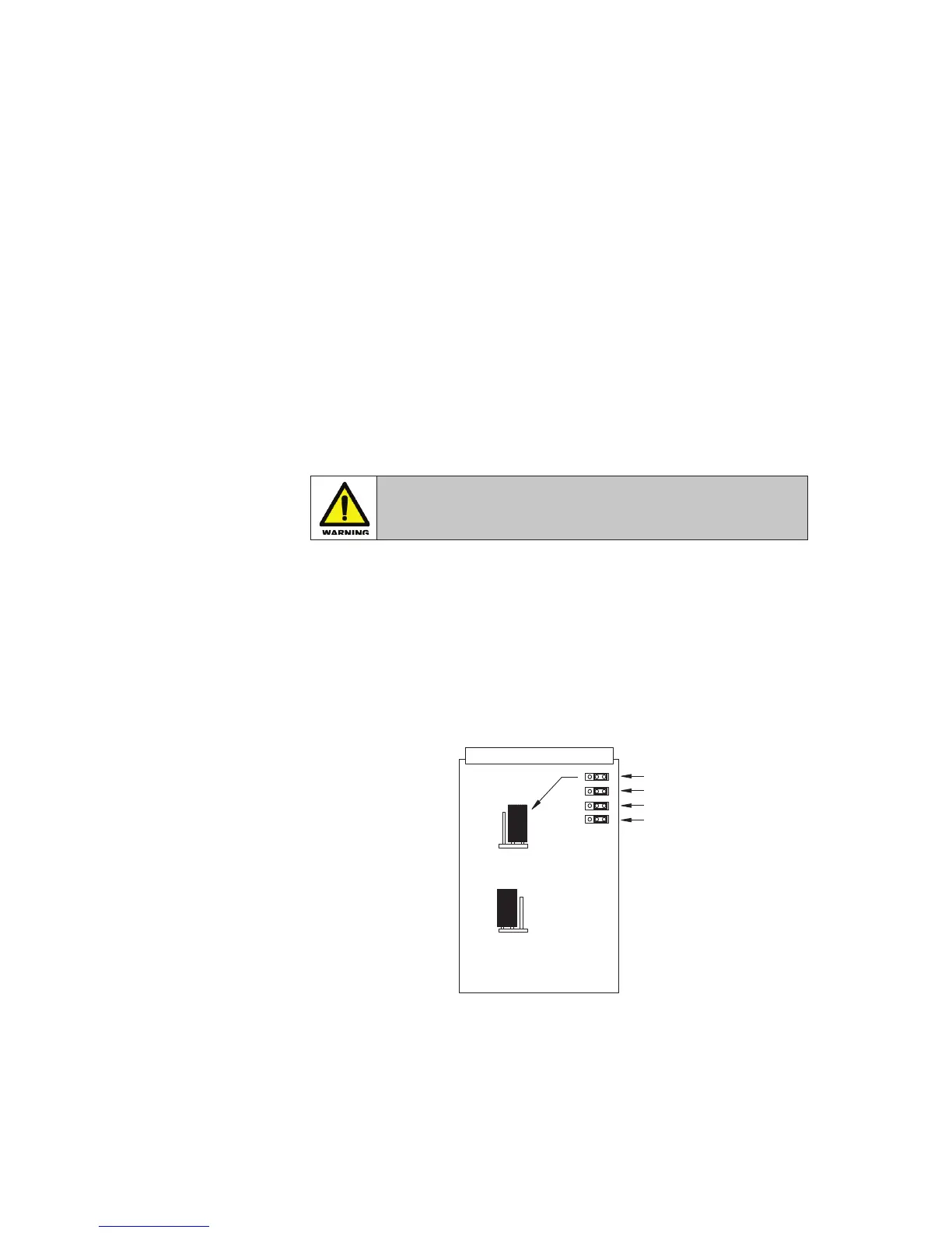
On standard RTK 725B systems each 4 channel alarm card is suitable for use with 24VDC or
125VDC signal inputs.
Each channel on the alarm card is equipped with a 3 pin header and 2 way shorting bar that
allows the user to set the input to match the required signal input voltage level. (24V or 125V)
5.2 Setting Inputs for use with 24VAC or 125VAC
RTK 725B signal inputs are bi-polar and therefore suitable for use with 24VAC or 125VAC.
Each channel on the alarm card is equipped with a 3 pin header and 2 way shorting bar that
allows the user to set the input to match the required signal input voltage level. (24V or 125V)
WARNING !
Remove ALL power from the unit and fully remove the card before changing
any jumpers
However when using AC inputs additional filters are added which result in a 25mS response time
before the alarm activates.
In systems using Time Stamping the alarm would still indicate the time the alarm first occurred
to the millisecond.
To set the signal supply voltage on each input to either 24VDC, 24VAC, 125VDC or 125VAC a
drop-down menu is provided in the Configuration Software. Selection is made under the Input tab
using the drop-down menu labelled “Field Contact Voltage (V)”
LK1LK2
LK3
LK4
125V
24V
24V
125V
125V
24V
OR
LK1LK1
SIGNAL SUPPLY
VOLTAGE SETTING
CHANNEL 1
CHANNEL 1
CHANNEL 2
CHANNEL 4
CHANNEL 3
SIGNAL SUPPLY
SET TO 24V
SIGNAL SUPPLY
SET TO 125V