75
11.3 Small Window versions.
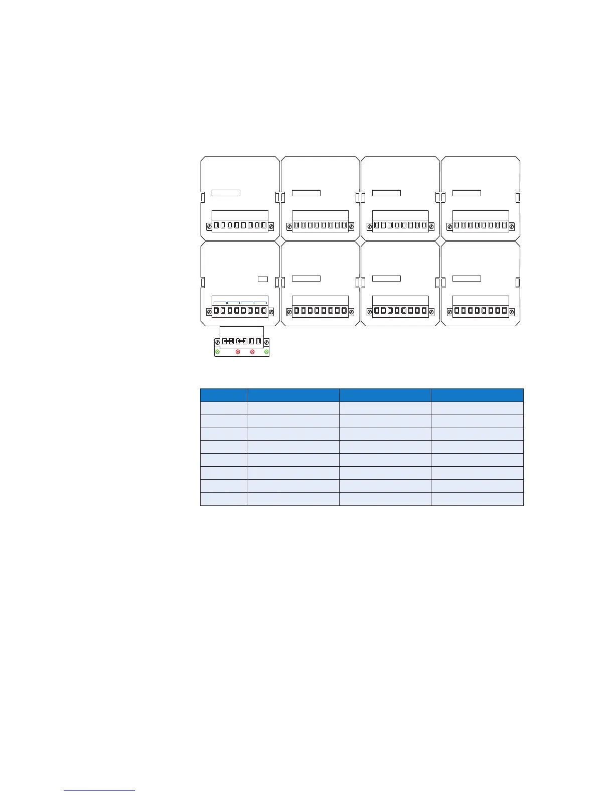
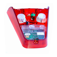
In the example shown 7 x four channel alarm cards plus 1 x common relay card would be fitted
in the cell positions indicated below:
Card Cell Type Cell Address
1 AP 0 0
2 AP 1 1
3 A 2 2
4 A 3 3
5 A 4 4
6 A 5 5
7 A 6 6
8 WR 7 7
DIL switch SW1 on each card in the system should be set to match the Cell number as
indicated in the diagram above which shows the rear view of a typical small window RTK 725B
Annunciator.
For details on how to set the address please refer to page 80.
WR
OV OV +V+V OVC +VC
Rx F1 F2 Tx
CR1 CR2 CR3 CR4
CHANNEL
AP
P1
EXT. PB
INPUTS
2
3
1 4 C
P3
P2
1 - 4
2C
INPUTS
2
3
1 1C4 4C3C
A
17 - 20
CHANNEL
1 2 4C1C4
3
3C2C
INPUTS
A
CHANNEL
9 - 12
1 2 4C1C4
3
3C2C
INPUTS
A
CHANNEL
25 - 28
3
21
4 1C 2C 3C 4C
INPUTS
A
CHANNEL
21 - 24
1 2
4C
INPUTS
1C4
3
3C
2C
CHANNEL
13 - 16
A
1
3
4
2
5 - 8
CHANNEL
CELL 6 CELL 4 CELL 2 CELL 0
CELL 7 CELL 5 CELL 3 CELL 1
AP
EXT. PB
INPUTS
P3
P2P1
C