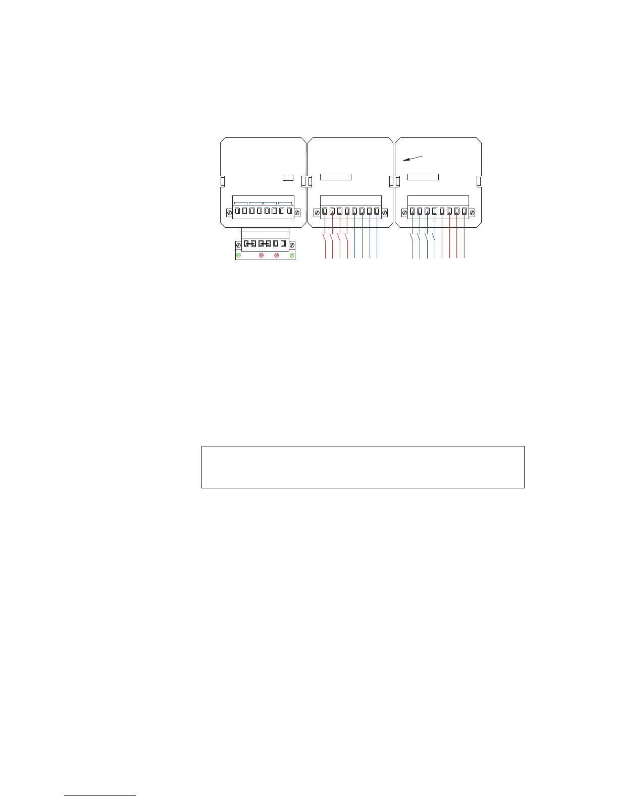
5.12 Optional Differential Input Version Wiring
As an option we can supply fully isolated inputs for each alarm way.
As the Inputs are bi-polar the user can switch AC or DC voltages as required.
In the above typical example cell 0 is shown with OV switched inputs and cell 1 is shown with
+24V switched inputs
Standard 24V/125V AC/DC Version
Each (4) channel alarm card is provided with a 3 pin header and 2 way jumper link per channel
which allows the user to select the input for use with either 24V or 125V as required.
Optional - 48V Version
Each (4) channel alarm card is set for use with 48V.
NOTE:
When differential inputs are used OV to OVC and +V to +VC must be linked otherwise a
permanent FC fault will appear.
WR
725B SMALL WINDOW VERSION TYPICAL REAR VIEW
OV OV +V+V OVC +VC
Rx F1 F2 Tx
CHANNEL
21
5 - 8
3C
INPUTS
4
3
1C 2C
A
4C
A
INPUTS
CHANNEL
3
1 2
1C4
1 - 4
4C2C 3C
CR1 CR2 CR3 CR4
EXT PB
INTERNAL SIGNAL
SUPPLY COMMON
CELL 2 CELL 1 CELL 0
(+) (+) (+) (+) (-)(-) (-)(-)
TYPICAL CUSTOMER
SUPPLIED
24VDC INPUTS
CH-5
CH-6
CH-7
CH-8
CH-5
CH-6
CH-7
CH-8
CH-1
CH-2
CH-3
CH-4
CH-1
CH-2
CH-3
CH-4
TYPICAL CUSTOMER
SUPPLIED
24VDC INPUTS
(+) (+) (+)(+)(-)(-) (-) (-)