iii
CONTENTS
1 INTRODUCTION ....................................................................1
1.1 General ..................................................................................1
1.2 Programmable Features ....................................................................1
1.3 Glossary of terms ..........................................................................2
1.4 Annunciator Model Code Definition .........................................................3-4
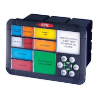
1.5 product overview ..........................................................................5
1.6 System Front View .........................................................................5
1.7 Number Of Alarms Per Cell ..................................................................6
1.8 Integral Pushbutton Location ................................................................6
1.9 Window Illumination .......................................................................6
1.10 LED Failure Indication ......................................................................7
1.11 Window Colours ...........................................................................8
1.12 Adding or Changing Film Legends ............................................................8
1.13 Filter & Bezel Spare Parts Numbers ...........................................................9
1.14 Laser Printed Legends ......................................................................9
1.15 Window Numbering System .................................................................9
1.16 Integral Pushbutton Module ................................................................10
1.17 Pushbuttons .............................................................................10
1.18 Watchdog Monitoring LED’s ................................................................10
1.19 USB Programming port ....................................................................11
1.20 CAL Mode ...............................................................................12
1.21 Signal Input Contact Status .................................................................13
1.22 Configuring Alarm Inputs for use with N/O or N/C field contacts ..................................13
1.23 Function Up / Down .......................................................................14
1.24 Channel Up / Down .......................................................................14
1.25 Remote Pushbutton Module ................................................................15
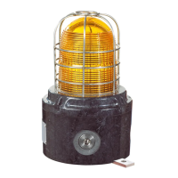
1.26 Audible Alarms ...........................................................................15
2 CELL TYPES. . . . . . . . . . . . . . . . . . . . . . . . . . . . . . . . . . . . . . . . . . . . . . . . . . . . . . . . . . . . . . . . . . . . . . .16
2.1 A Cell Detail (Alarm Cell) ...................................................................16
2.2 A Cell - Differential Input Version ............................................................17
2.3 AR Cell Detail (Alarm – Relay Cell) ...........................................................18
2.4 AR Cell - Differential Input Version ...........................................................19
2.5 AP Cell Detail (Alarm – Pushbutton Cell) ......................................................20
2.6 APR Cell Detail (Alarm / Pushbutton – Relay Cell) ..............................................21
2.7 AP6 Cell Detail (Alarm Card - Remote Pushbutton) ..............................................22
2.8 AWR Cell Detail (Alarm – Watchdog Relay Cell) ................................................23
2.9 AS Cell Detail (Alarm – Supply Cell) ..........................................................24
2.10 AS Cell - Differential Input Version ...........................................................25
2.11 S Cell Detail (Supply Cell) ..................................................................26
2.12 SS Cell Detail (Supply - Supply Cell) .........................................................27
2.13 WR Cell Detail (Watchdog - Relay Cell) ........................................................28
2.14 WRS Cell Detail (Watchdog / Relay - Supply Cell) ...............................................29
2.15 WRR Cell Detail (Watchdog / Relay - Relay Cell) ................................................30
2.16 Optional WR Cell Detail (Watchdog - Relay Cell) ................................................31
2.17 WRP Cell Detail (Watchdog Relay Card - Remote Pushbutton) ....................................32
2.18 AC Cell Detail (Alarm – Comms Cell) .........................................................33
2.19 APC Cell Detail (Alarm – Pushbutton - Comm’s Cell) ............................................34
2.20 C Cell Detail (Comm’s Cell) .................................................................35
2.21 WRC Cell Detail (Watchdog / Relay - Comm’s Cell) ..............................................36
2.22 CE Cell Detail (Comms Enhanced Cell) .......................................................37
2.23 ACE Cell Detail (Alarm – Comm’s Enhanced Cell) ...............................................38
2.24 WRCE Cell Detail (Watchdog / Relay - Comm’s Enhanced Cell) ....................................39
2.25 CEC Cell Detail (Comm’s Enhanced – Comm’s Cell) .............................................40
2.26 PCE Cell Detail (Remote Pushbutton - Comm’s Cell) .............................................41