49
5.7 Optional 24VAC Signal Input Wiring
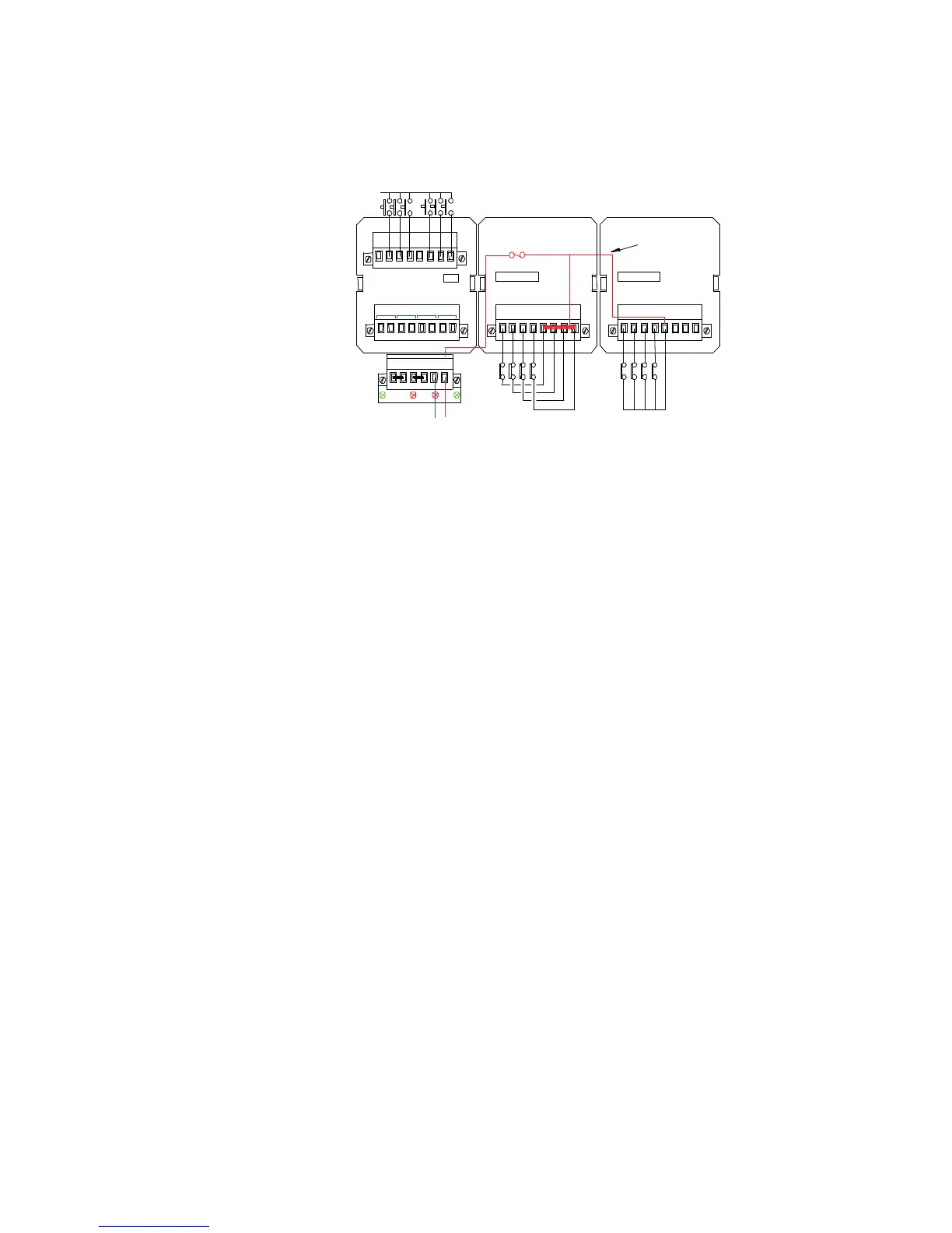
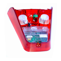
Each channel on the alarm card is provided with a 3 pin header and 2 way shorting bar which
allows the user to select the inputs to operate on 24V
LED F2 is used to indicate that the signal supply, (+VC), fuse has blown.
As all *C terminals are internally linked the customer can connect each input contact to a
dedicated terminal as shown in the middle cell or a single feed can be used for multiple contacts
as shown in the right hand cell.
The common return for all remote pushbuttons is +V (+24VDC)
To set the signal supply voltage on each input to 24VAC a drop-down menu is provided in the
Configuration Software. Selection is made under the Input tab using the drop-down menu labelled
“Field Contact Voltage (V)”