13.4.5 Write Multiple Coils – Function 15 – Response
Register Address
Number of coils that have been written
Quantity
This represents the number of coils (Inputs), the user wishes to be written
Typical Example of Message Format – Entry Level Comm’s
To write to all of the inputs available on the first alarm card in the system the user would need
to send the following message
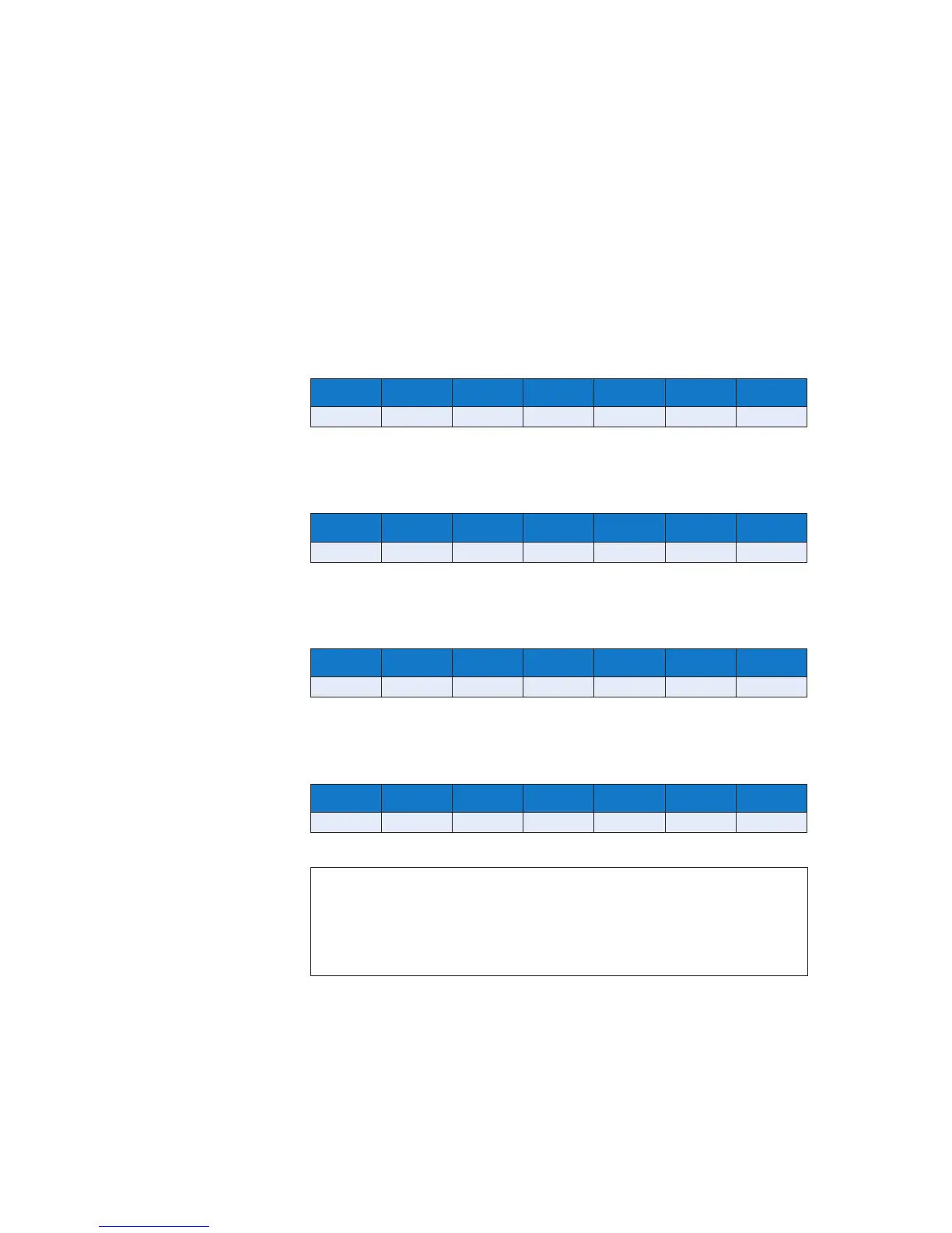
ADDRESS FUNCTION REGISTER
ADDRESS
No. of
REGISTERS
BYTE COUNT DATA ERROR
CHECK
01 OF 00 00 00 04 01 OF 7E 92
To write input 3 to the normal state on the second alarm card in the system you would need to
send the following message
ADDRESS FUNCTION REGISTER
ADDRESS
No. of
REGISTERS
BYTE COUNT DATA ERROR
CHECK
02 OF 00 02 00 01 01 00 17 42
To write the third pushbutton input on alarm card 1 to abnormal you would need to send the
following message
ADDRESS FUNCTION REGISTER
ADDRESS
No. of
REGISTERS
BYTE COUNT DATA ERROR
CHECK
01 OF 00 06 00 01 01 01 67 57
To write the third pushbutton input on alarm card 1 to normal you would need to send the
following message
ADDRESS FUNCTION REGISTER
ADDRESS
No. of
REGISTERS
BYTE COUNT DATA ERROR
CHECK
01 OF 00 06 00 01 01 00 A6 97
NOTE
On systems supplied before 30st July 2010 the input status is OR’d with the actual
contact state. If the input is serial only please ensure the contact type is set to Normally
Open and no customer wiring is made to the customer terminals located on the rear of
the associated cell.
With serial inputs 0 = Input Normal and 1 = Input Abnormal