73
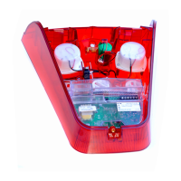
5. Once the rear cover has been removed the associated card can be withdrawn by pulling
on the socket.
6. Please note each card in the system has its own unique address and it is important that
the user notes the address if removing multiple cards or replacing a card.
7. Once a card has been replaced the plastic cover can be clipped back into position, the
terminal block can be re-connected and the screws tightened to lock it in place.
IMPORTANT
8. If a card has been replaced the user will need to download the original software
configuration to the unit to ensure that the features of the new card match the original one.
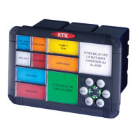
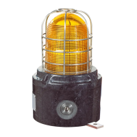
Connected Equipment
Equipment such as remote push buttons or sounders may be connected to the 24V power
output of the annunciator.
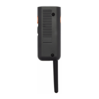
WARNING !
The RTK 725B & 725C systems described herein operate on a logic voltage
of 24VDC and as standard 24VDC is used for the field contact supply
voltage.
Internal or External power supplies using higher voltage AC/DC primary
sources and optional high voltage field contact voltages may be present.
If this is the case ensure that the annunciator is powered down before
working on the unit or any connected apparatus.