178
Technical Publication Document NO: SYSTEM-007-ENG (Ver.1.1)
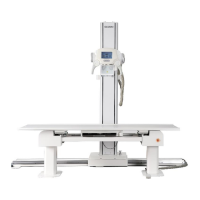
HF-525Plus Installation, Operation and Service Manual
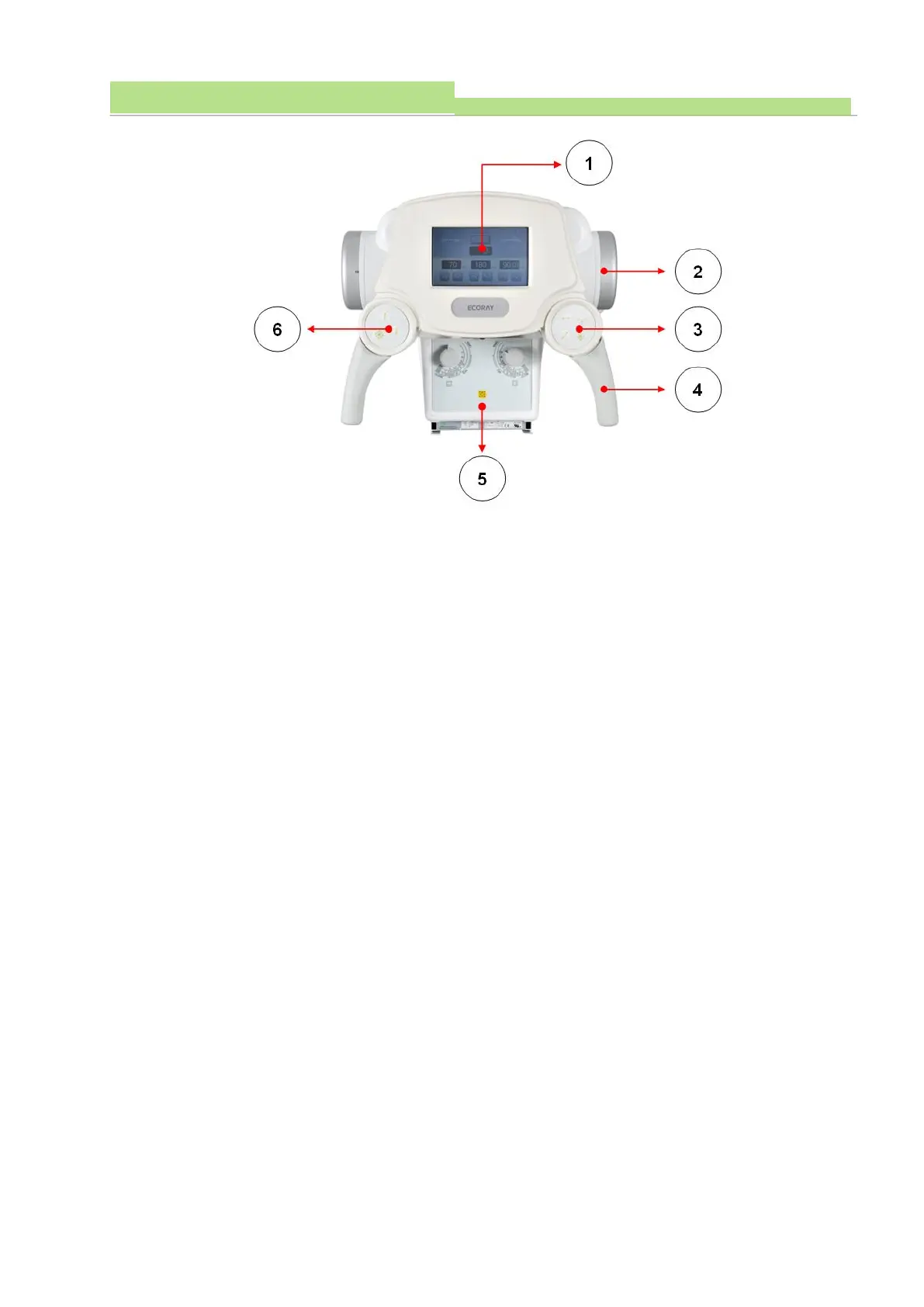
● Figure1
(1) The LCD display (Figure 1) displays the X-ray irradiation condition set in the X-ray console and the
rotation angle of the X-ray tube. (See LCD display window of 7.3.1 Handle bar)
● Figure2
(1) An electron tube where X-rays are generated (Figure 2).
(2) The X-ray tube is connected to the HVT and supplies high-voltage power to generate the X-ray.
● Figure3
(1) HF-525 Plus’ Tube Stand and Ceiling are fixed by electromagnet.
(2) These buttons are front, back, left, right and all lock switch buttons (Figure 3) of Tube Stand and
Ceiling Unit. When the switch is "Off", it is in the LOCK state and when the switch is "ON", it is in
the LOCK Free State.
(3) The lock switch (Figure 3) is in the LOCK state before the switch operation and in the LOCK Free
State when the switch is in operation.
● Figure4
(1) This is the Tube Stand and Ceiling Device handlebar.
● Figure5
(1) This is a device for controlling the X-ray irradiation area.
● Figure6
(1) HF-525 Plus’ Tube Stand and Ceiling are fixed by electromagnet.
(2) These buttons are front, back, left, right and all lock switch buttons (Figure 3) of Tube Stand and
Ceiling Unit. When the switch is "Off", it is in the LOCK state and when the switch is "ON", it is in
the LOCK Free State.
(3) The lock switch (Figure 6) is in the LOCK state before the switch operation, and the LOCK Free
State when the switch is in operation.