198
Technical Publication Document NO: SYSTEM-007-ENG (Ver.1.1)
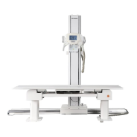
HF-525Plus Installation, Operation and Service Manual
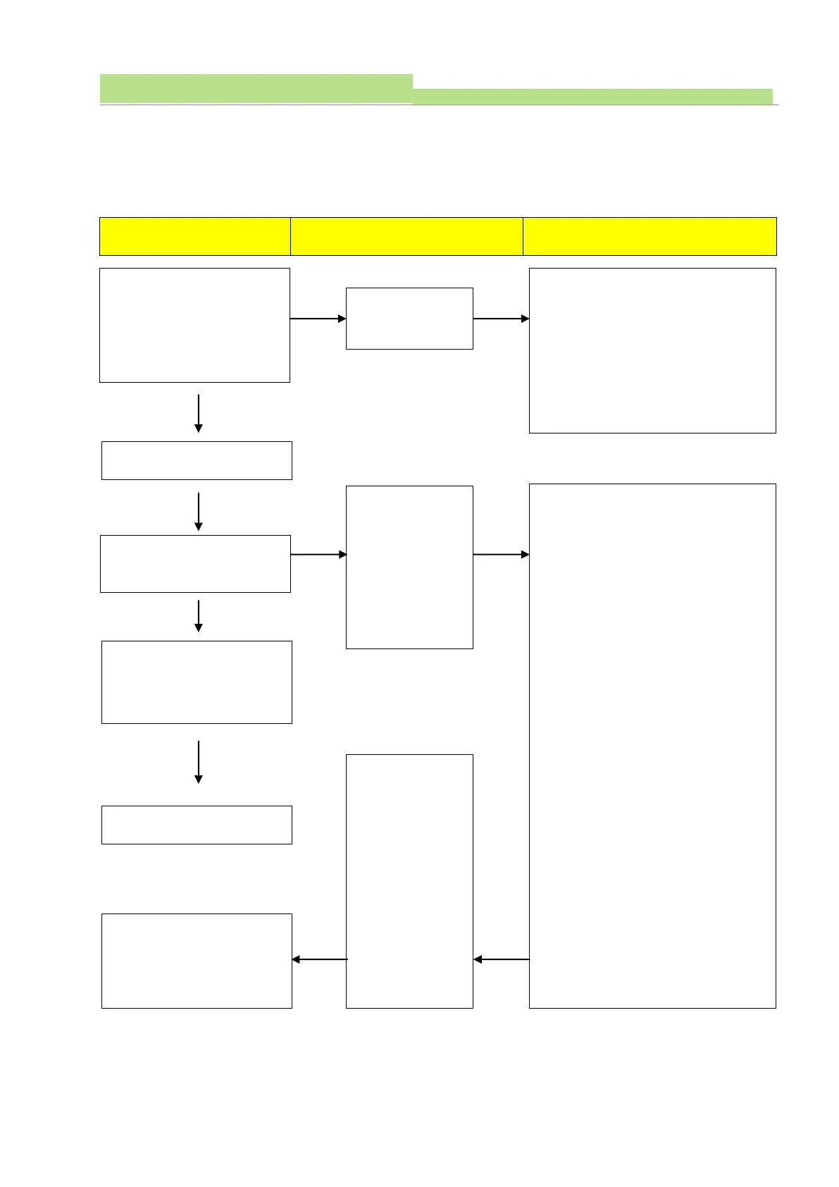
2) Check Procedures 1
(1) Board Name: XR7-CnD
(2) Functions: This board controls charge/discharge of Main Condenser.
(3) Followings are the check procedures for XR7-CnD board when charge/discharge trouble.
Provide main input power to
generator and check if LED
(817) is ON.
*Before the power ON at the
console.
1. Check Connector (P802) condition.
2. Check voltage TP803 (GND) with
TP804 (5V) (Normal: DC 5V ±0.2V)
3. Check voltage TP803 (GND) with
TP805 (12V).
(Normal: DC 12V ±0.2V)
1. Check P803 connecting condition,
and check voltage (Normal: 230VAC)
2. Check fuse condition (F801)
3. Check lighting condition (D816)
(Normal: Green)
4. Check P805 connecting condition,
and check voltage
(Normal: 1 with 4 ->310VDC±10V)
5. Check P802 connecting condition.
6. Check voltage TP803 (GND) with
TP804 (5V). (Normal: DC 5V±0.2V)
7. Check voltage TP803 (GND) with
TP805 (12V).
(Normal: DC12V ±0.2V)
8. Check relay (RLY801) working
condition. (Normal: it works if push
the “ON” button on the console, it
will be stop if main condenser
charged by 90%)
9. Check relay (RLY802) working
condition. (Normal: If RLY801 stops,
RLY802 works at once)
Standby lamp is flickering of
Console
Standby lamp turned to
green and FND display goes
enabled..
Frequency adjusting method
described at
charging/discharging part
In case of Relay
(RLY801, 802) do
not work
correctly, check
the frequency at
Test point (TP802,
803) and make
sure if it is 75kHz
or not.
Standby lamp
flickering then
turns green and
error code
(CHA Err)
displayed.