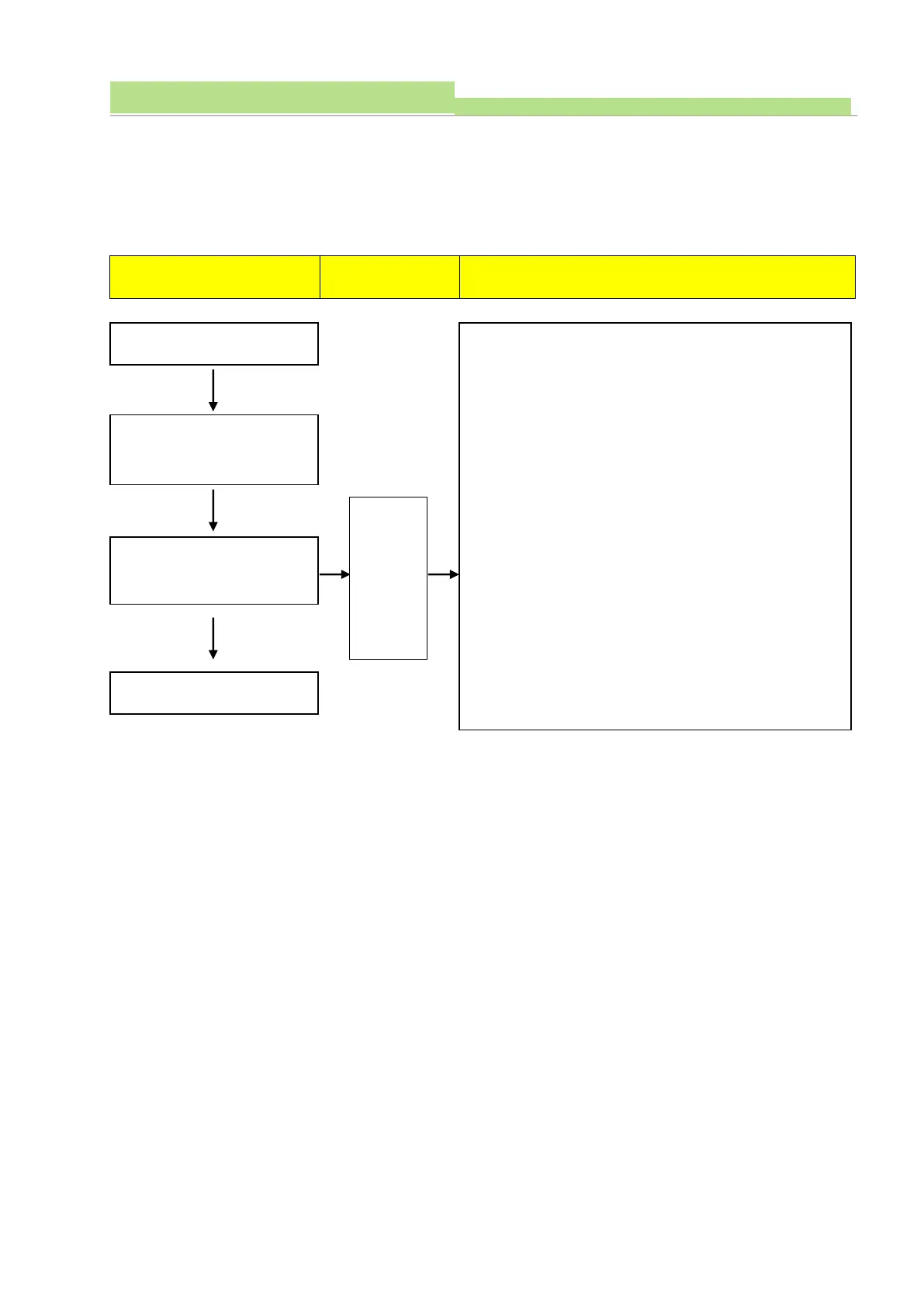
1. Power OFF before the circuit check.
2. Check resistance value between P502 pin 1 & 2, and check
Diode voltage on Driver board.
(Detection point is same and measure it at Power OFF status
only)
(Normal: resistance -> 1 ㏀ ± 50Ω,
Diode voltage -> 0.7VDC ± 0.1V)
3. Measure the resistance between P502 pin 3 & 4 and voltage
at Diode in Power OFF condition.
(Normal: Resistance -> 1㏀ ± 50Ω,
Diode voltage -> 0.7VDC ± 0.1V)
4. Measure resistance value between P503 pin 1 & 2 and Diode
voltage under Power OFF status.
(Normal: Resistance -> 1㏀ ± 50Ω,
Diode voltage -> 0.7VDC ± 0.1V)
5. Measure resistance between P503 pin 3 & 4 and Diode
voltage at Power OFF status.
(Normal: Resistance
Diode voltage -> 0.7VDC ± 0.1V
)