1. Check communication cable between OP console and
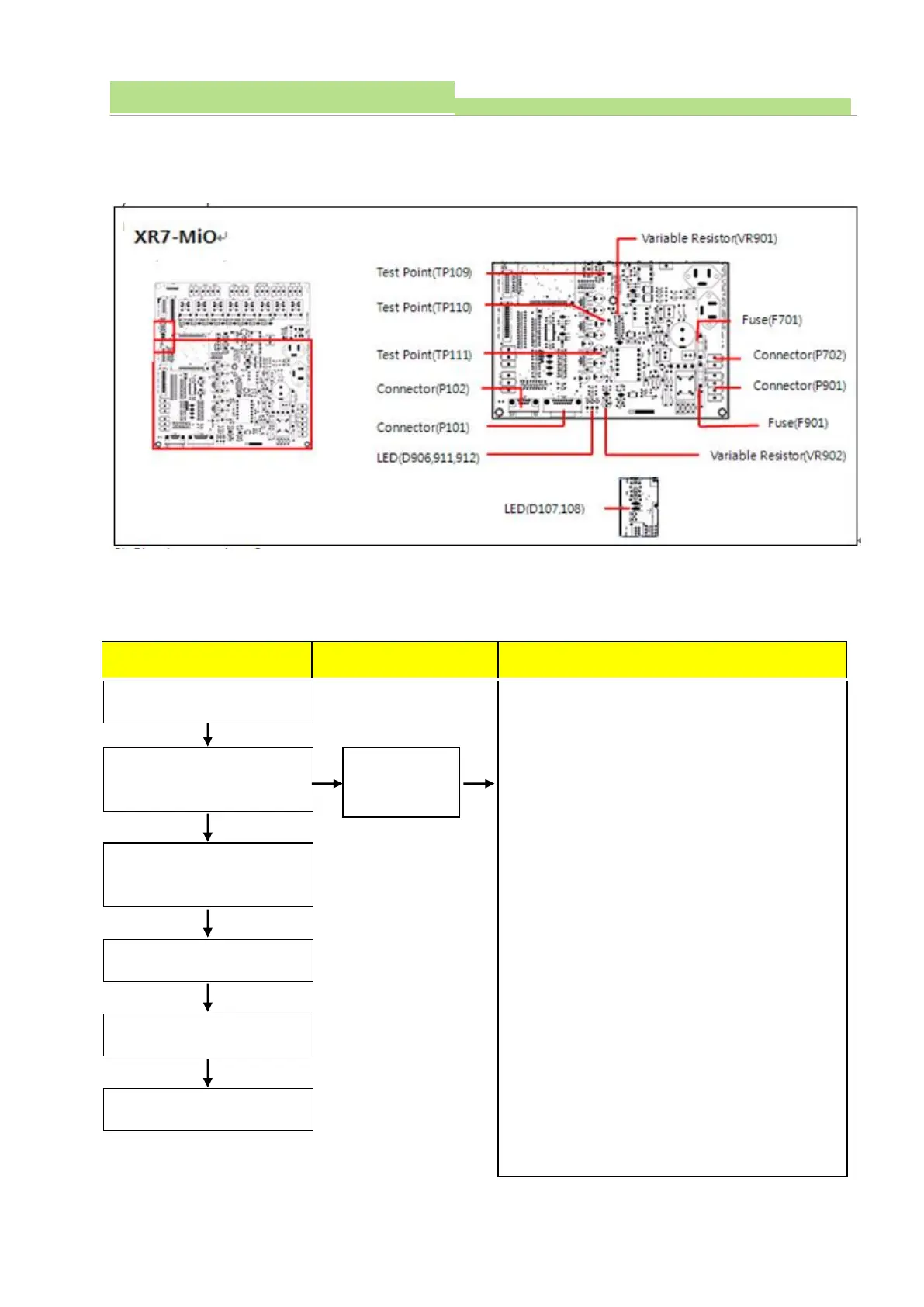
Connector (P101).
2. Check cable connection between ECO-AEC
(AEC Board) and Connector (P102).
3. Check LED (D107, 108)
Normal: D107 flickers during data setting (green)
Abnormal: D108 light ON (Red)
4. Check LED (D906, 911, 912)
Normal: D906 lights ON before Power On
D911, 912 light ON after Power On
Abnormal: No LED light ON after Power On
5. Check the Connector (P901) and voltage.
(Normal: 230VAC)
6. Check the Fuse (F901)
7. Measure the voltage Test point (TP109) and
Test point (TP110)
(Normal: 7.5VDC ±0.1V)
8. In case the TP110 voltage is not normal, adjust VR901
to fix 7.5VDC.
9. Measure the voltage Test point (TP109) and Test point
(TP111)
(Normal: 15VDC ±0.1V)
10. In case Test point (TP111) voltage is not normal,
adjust VR902 to meet 15VDC.