EasyManua.ls Logo

Ecoray HF-525Plus - Page 216

Ecoray HF-525Plus
233 pages
Print Icon
To Next Page IconTo Next Page
To Previous Page IconTo Previous Page
Loading...
216
Technical Publication Document NO: SYSTEM-007-ENG (Ver.1.1)
HF-525Plus Installation, Operation and Service Manual
5) Consist of part 2
6) Check procedure 2
(1) Board Name: ECO-AEC Board
(2) Functions: Controlling Ion Chamber
(3) Check communication condition when communication trouble occurred between input/output signal of Ion
Chamber and circuit error. And check procedures are as follows.
Normal Operation
Under defective
How to check and repair
Err AEC comes
on the display
Turn ON power of console
Self-diagnosing automatically by
program
System is ready to be used.
Select AEC function
Set exposure value
X-ray exposure
1. Check communication cable wiring condition between
OP console and AEC board.
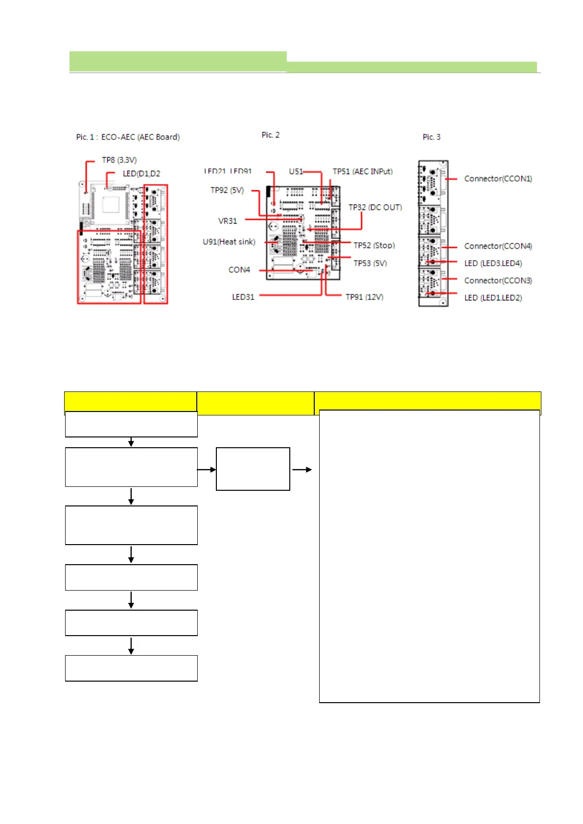
2. Check the Connector (CCON1).
3. Check Connector (CCON3, 4).
4. Check the console and Connector (CON4) cable
connections.
5. Check LED (D1, D2, LED31, LED91) lighting condition.
Normal: LED (D1, D2, LED31, LED91) light ON
6. Check LED (LED21) lighting condition.
Normal: LED21 flickers during data communication.
7. Check voltage U91 (Heat sink. GND) with TP91
Normal: 12VDC ±0.5V
8. Check voltage U91 (Heat sink. GND) with TP53
Normal: 5VDC ±0.3V
9. Check voltage U91 (Heat sink. GND) with No.11 of
U51. Normal: -12VDC ±0.5V
10. Check voltage U91 (Heat sink. GND) with TP92
Normal: 5VDC ±0.3V

Table of Contents

Related product manuals