215
Technical Publication Document NO: SYSTEM-007-ENG (Ver.1.1)
HF-525Plus Installation, Operation and Service Manual
3) Consist of part 1
4) Check procedure 1
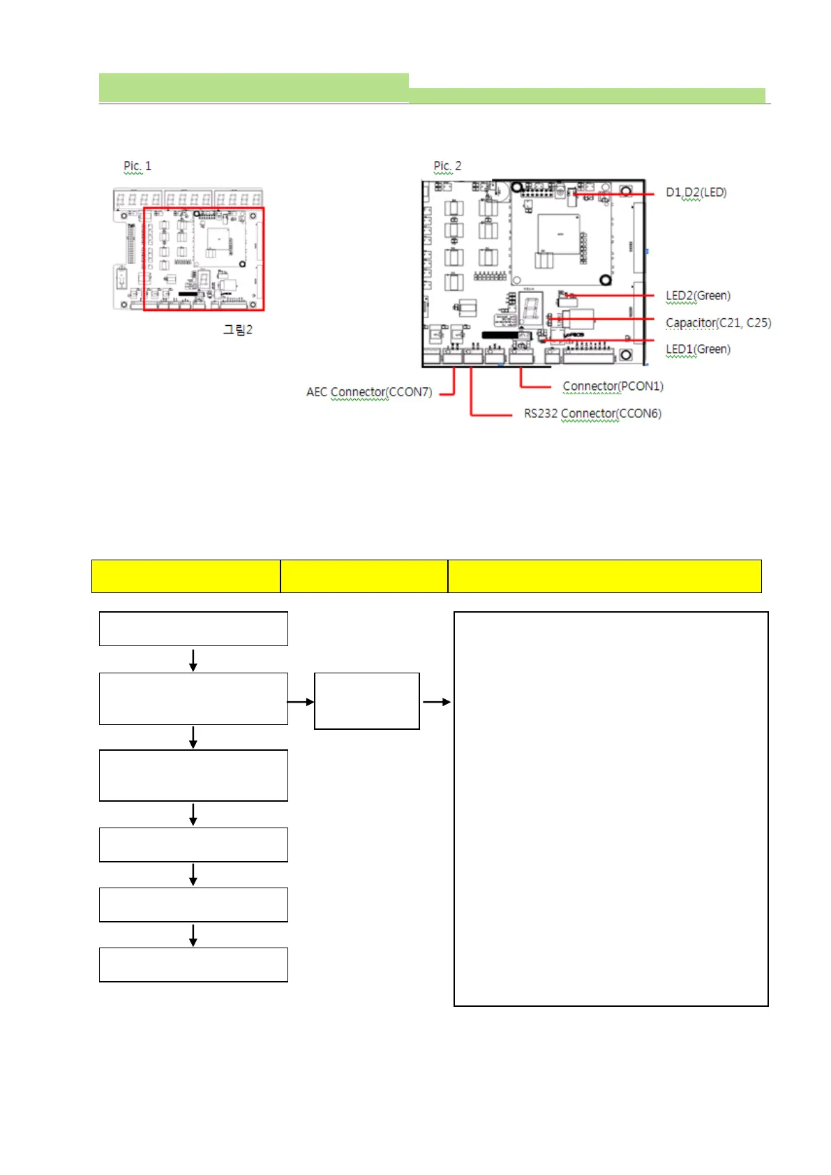
(1) Board Name: XR7-CON Board
(2) Functions: Controlling Ion Chamber
(3) Check communication cable condition and then check circuit when communication troubles occurred
between console and XR7-MiO Board and Ion Chamber. And check procedures are as follows.
1. Check communication cable wiring condition (Console
with X-ray generator)
2. Fix the Connector (CCON7).
3. Fix the Connector (CCON6).
4. Fix the Connector (PCON1).
5. Check LED lighting (LED2, D1, D2)
Normal: LED (D1, D2) light ON.
6. Check the voltage between Connector (PCON1) pin 1
& 4. Normal: 7.5VDC ±0.2V
7. Check the voltage of Capacitor (C21)-both ends
Normal: 7.5VDC ±0.1V
8. Check the voltage of Capacitor (C21)-both ends
Normal: 5VDC ±0.1V
Err AEC comes
on the display
Self-diagnosing automatically by
program
System is ready to be used.