46
Technical Publication Document NO: SYSTEM-007-ENG (Ver.1.1)
HF-525Plus Installation, Operation and Service Manual
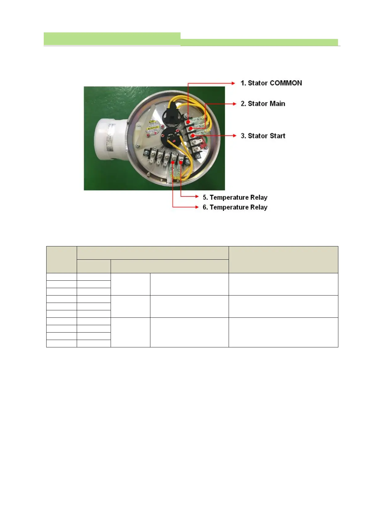
● Checking X-Ray Tube Anode Side’s Composition
● Connecting Cable between X-Ray Tube Anode Sided and GC Board CON703
WARNING ▶
X-ray tube Anode Stator wiring is must correctly with recommended by X-ray tube manufacturer. Never
connect terminal No.1 to No. 5 and No. 6. The terminal pins of the high voltage cable are extremely
delicate and easily damaged. And then, handle them with very carefully.
■ Connecting HV Cable between HVT’s Anode, Cathode and X-Ray Tube’s Anode, Cathode
● Before Connecting HV Cable, and Always Closing Receptacle socket for Getting Dirt.