54
Technical Publication Document NO: SYSTEM-007-ENG (Ver.1.1)
HF-525Plus Installation, Operation and Service Manual
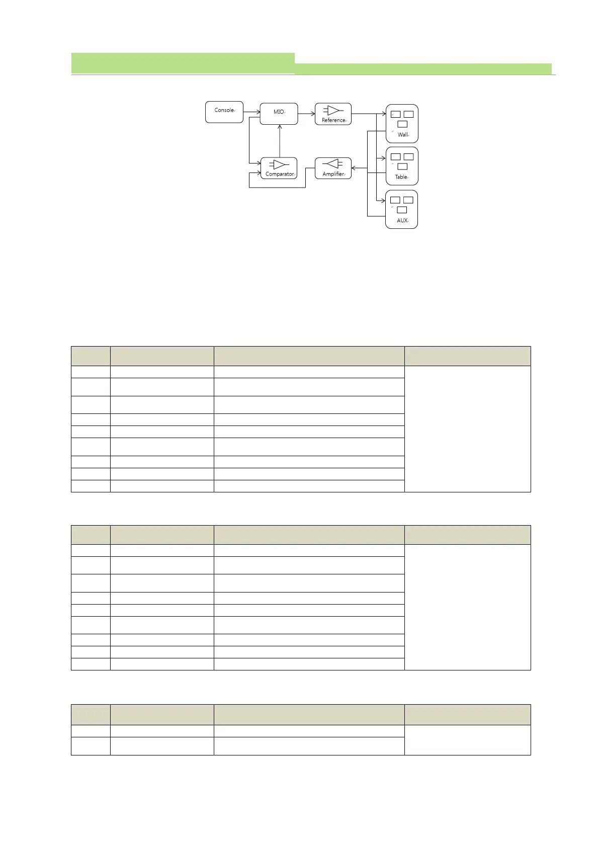
● AEC Chamber Control board’s Block Diagram
● AEC Chamber Setting
From (AEC) Chamber’S Pre-amplifier To signal to AEC Board, must be Negative. Chamber Signal is
different from different manufacturers, so need to check before device Installation.
● RS232 (port), and connect to AEC Chamber & AEC Chamber control board’s P801, P802, P803.
Connector Pin composition is shown below.
P801’s Composition of Connector Pin (FOR Auxiliary)
P802 Connector Pin Composition (FOR Table)
P802 Connector Pin Composition (FOR Upright stand)
P801, P802, P803’s Pin
Composition is same
and, AEC Chamber’s
Auxiliary Signal and
P801, Table Signal,
P803, Upright stand
Signal, and P802 Signal
all Connected.
P801, P802, P803’s Pin
Composition is same
and, AEC Chamber’s
Auxiliary Signal and
P801, Table Signal,
P803, Upright stand
Signal, and P802 Signal
all Connected.
P801, P802, P803’s Pin
Composition is same
 Loading...