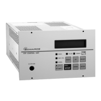
SCU-800 Control Unit for Turbomolecular Pump
Table 29 shows the status of LCD, LEDs, and REMOTE output signals at a power failure.
Duration of
power failure
Backup
rotational speed
or more
Less than
Backup
rotational speed
Table 29 - States of LCD, LEDs and REMOTE output signals at a power failure
7.1.2 Operation after a power recovery
1. The STP pump continues decelerating, and power failure detection is reset automatically.
At this time, the "POWER" LED illuminates and the "FAILURE" LED extinguishes. Also, POWER
OUT pins (9)–(28) is closed, and a failure signal is reset between ALARM OUT pins (14)–(33)
and (15)–(33) of the "X7 REMOTE" connector.
2. When the START operation is performed after a power recovery, the STP pump reaccelerates
even while it is in BRAKE state.
However, the SCU-800 may detect excessive vibration when power is recovered after the rotor
lands on the touch down bearing (see Section 7.1.4). In this case, the STP pump once stops and
cannot reaccelerate until the RESET operation completed (see Section 4.5.7).
Note: It is recommended to establish a procedure so that the power can be supplied to the SCU-800
immediately after a power recovery.
7.1.3 Abnormal state of magnetic bearing
CAUTION
When an abnormality/error occurs in the magnetic bearing, check the STP pump as well as the
SCU-800. If "FAILURE" cannot be released after reset operation, contact Service office.
When the magnetic bearing does not function normally due to a breakage of the STP connection
cable, disconnection of connectors or any abnormality/error of the STP control circuit, the rotor lands
on the touch down bearing and stops. The "FAILURE" LED illuminates and the LCD displays error
message "Disturbance *".

 Loading...