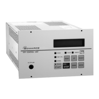
SCU-800 Control Unit for Turbomolecular Pump
3.3 Rear panel
X 3 B
X5 TMS
X 3 B
ON
X 7 RE M O T E
F2 4A(F)
F1 4A(F)
X2
(L2)
N
L
(L1)
PE
M A I N P O W E R
OFF
AC POWER
!
X6
!
!
X 3 A
X 1 P C O N N E C T O R !
Serial port COM1 X3A, X3B
Figure 11 - SCU-800 rear panel
A hazardous live voltage may exist at the connectors that are marked with the
warning sign
. DO NOT touch the terminal. Doing so may result in electric shock.
When connecting/disconnecting the connecter, always power off the SCU-800 (turn
the MAIN POWER "OFF") and isolate (Lockout/Tagout) the electrical energy source,
water and gas, and other energy sources on the vacuum equipment.
Main power connection (240 Va.c. maximum)
Main power circuit breaker
Ground (Earth) connection terminal
Serial communication connection RS485
Remote connection (125 Va.c. maximum)
STP pump connection (92 Va.c. maximum)
Serial communication connection RS232/RS485 (shard use)
TMS unit connection (240 Va.c. maximum)
Fuses for TMS unit (optional accessory)
Table 4 - SCU-800 rear panel connection

 Loading...