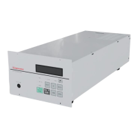
SCU-800 Control Unit for Turbomolecular Pump
SERIAL COMMUNICATION
PROTOCOL
2. Serial Port COM2 (exclusively used in the RS485)
Connect D+/D- to connector X6 on the rear panel (D-Sub 9 pin, socket) according to Table 16. Other
pins are reserved for Input/Output remote function, accordingly, there is no connection to these pins.
Refer to Section 5.2.2.
Table 16 - X6 pin position
Figure 33 - Connector X6 (D-sub 9)
Note: The connector X6 is fitted using M2.6 screws.
3. Serial Port STP-Link (exclusively used in the RS232)
Connect signal transmitted from the PC to connector X8 on the front panel. Connect the optional
STP-Link communication cable to the PC.
 Loading...