Chapter 3 Description of the Machine
3-1
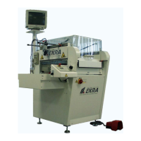
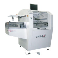
E1 Semi-automatic screen printer
System Manual
EKRA / Doku Eisermann 03_SYSTEM_PDF.FM
30.8.02
3 Description of the Machine
General
The E1 screen printer processes solder pastes (precious metal pastes),
resistor pastes, dielectric materials, silicones, conductive adhesives, lac-
quers and protective coatings to a degree of accuracy and quality that is
absolutely essential for the production of sophisticated film circuitry such as
hybrids, multilayers, LCDs, components, chip carriers and solar cells, and
for SMD technology in general.
Printing can be performed on flexible or rigid base materials such as glass,
ceramics, plastic or metal, with a material thickness of up to 10 mm.
The E1 semi-automatic screen printer is operated with the aid of a control
panel and other operating elements.
A programmable logic controller (PLC) takes care of control of the
machine. The supporting frame is made of rugged Itemprofil.
The printing table is finely adjustable in the X, Y and theta directions. In
conjunction with the manual optical positioning system (MOPS), it is per-
fectly possible to achieve printing results in the fine pitch range.
Printing sequence
The operator sets up the printing stencil in the machine by hand. Two
clamping cylinders fix the stencil in position in the guideway.
The snap-off is adjusted by hand using a handwheel on the right-hand side
of the machine. The value is indicated by a high-precision indicating instru-
ment.
The operator adjusts the squeegee pressure with the pressure regulator on
the control desk.
The solder paste is applied to the stencil by hand. The squeegee parame-
ters, such as squeegee speed, front and rear squeegee position, printing
mode and separation speed, are entered in the main menu on the control
panel. The plastic cover over the print area must remain closed during
printing.
The operator places a PCB in the PCB holder on the printing table by hand.
The PCB clamping switch triggers the PCB clamping system, and the PCB
is fixed in place in the holder. The printing process is started with the foot
switch. The printing table moves in the X-direction from the loading position
on the left to the printing position in the machine. The squeegee unit moves
in the Y-direction from the rear towards the front. The printing process pro-
ceeds according to the printing mode. When printing is completed, the
printing table moves out to the loading position. The operator removes the
PCB from the printing table.