Chapter 3 Description of the Machine
3-7
E1 Semi-automatic screen printer
System Manual
EKRA / Doku Eisermann 03_SYSTEM_PDF.FM
30.8.02
Squeegee unit
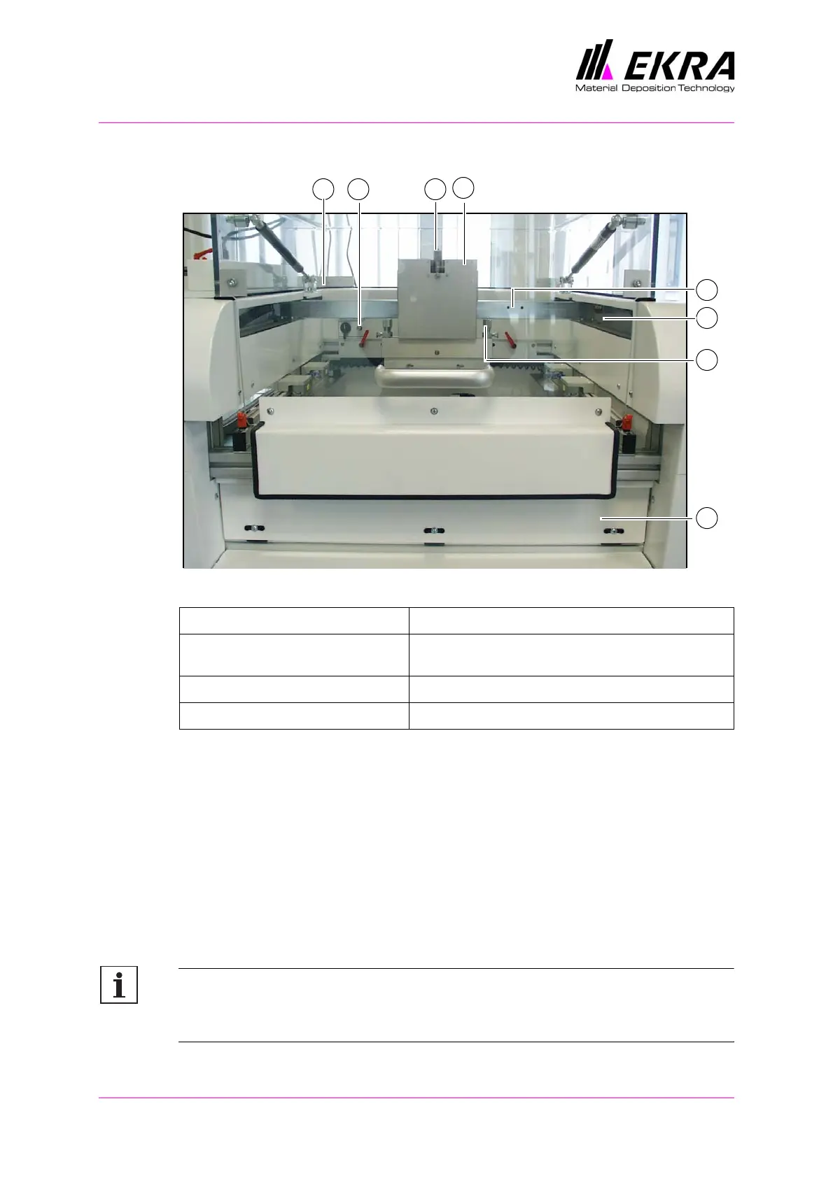
Fig. 10. Squeegee unit
The squeegee unit is fitted in the upper part of the machine. It consists of
the squeegee head with a printing squeegee and a flooding squeegee, the
squeegee drive and the squeegee guideway with ball-bearing bushes.
The squeegee head consists of two units for the printing squeegee and the
flooding squeegee. Three precision-guided pneumatic cylinders for each
unit execute the squeegee stroke. The down stop can be adjusted using
the down stop micrometers. The pivoting range of the individual squeegees
can be limited mechanically by adjusting the pivot-stop screws.
To allow cleaning of the screen the cleaning flap can be opened forwards,
enabling the underside of the screen to be cleaned.
Note:
If the screen is removed for cleaning, a new alignment procedure is
required.
1 Cleaning flap 5 Pivot-stop screws
2 Squeegee guideway with
ball-bearing bushes
6 Down stop micrometers
3 Squeegee head 7 Pneumatic connection, film tensioning frame
4 Squeegee beam 8 Screen clamping switch
1
2
5
3
4
678