42
GENERAL DIMENSIONS
Plan the installation so that the electrical connection, gas shut-off valve, and pressure regulator are accessible
from the front of the cabinet.
25”
B
Top of
counter
to combustible
sides walls
above the range
Fig 2
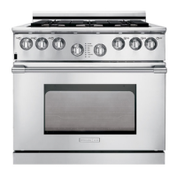
E30GF74GPS, E36GF75GPS,
E36GF76GPS
utility
location
Cutout Dimensions
Model “A” “B’
E30GF74 Series 30” (762 mm) 30 1/16” (764mm)
Minimum Recommended
E36GF75 Series 36” (914) 36 1/16” (916 mm)
Minimum Recommended
E36GF76 Series 36” (914) 36 1/16” (916 mm)
Minimum Recommended
13”