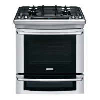
53
gas igniter/re-igniter module
and an igniter in each burner.
When the shaft of the valve is rotated from the off posi-
tion the contacts of the igniter switch close and remain
closed as long as the burner is on. This connects L1
to the module terminal for that burner. The module
has two jobs; rst to ignite the burner and once the
burner has been ignited, to monitor the ame. When
power is applied to the module, inside the module
two things happened. First power is supplied to the
step-up transformer, which in turn supplies power to
the charging circuit and second an electrical signal is
generated and applied to the igniter of the burner that
is being ignited.
The gas passes through the center hole into the sim-
mer burner head. The gas exit the simmer burner head
through the simmer burner ports.
As a gas exits the simmer burner ports, it mixes with
secondary air that is provided by the holes in the burner
base, through the holes in the burner head and slots
in the simmer burner base and forms a combustible
mixture. The combustible mixture is then ignited by
the igniter.
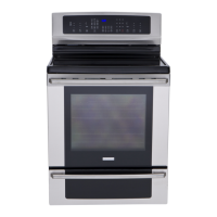
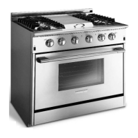
Top burner ignition and reignition system
The burner ignition and reignition system is made up
of the ignition switches, that are mounted to the top
burner valves,