G3 Series EtherCAT
TM
Technical Manual
10-95
Subject to change without notice
www.asco.com/g3
One High Current Analog I/O per Connector – M12 Female Modules
Module
Part No.
Signal Type
Short Circuit
Protection
Protection Status
Output Points Input Points
BYTE Bit 7 Bit 6 Bit 5 Bit 4 Bit 3 Bit 2 Bit 1 Bit 0
X
X+1
No. 1
Output No.
1
Output No.
1
Output No.
1
Output No.
1
Output No.
1
Output No.
1
Output No.
1
X+2
X+3
No. 2
Output No.
2
Output No.
2
Output No.
2
Output No.
2
Output No.
2
Output No.
2
Output No.
2
BYTE Bit 7 Bit 6 Bit 5 Bit 4 Bit 3 Bit 2 Bit 1 Bit 0
X
Input No. 1 Input No. 1 Input No. 1 Input No. 1 Input No. 1 Input No. 1
X+1
No. 1
Input No. 1 Input No. 1 Input No. 1 Input No. 1 Input No. 1 Input No. 1 Input No. 1
X+2
Input No. 2 Input No. 2 Input No. 2 Input No. 2 Input No. 2 Input No. 2
X+3
No. 2
Input No. 2 Input No. 2 Input No. 2 Input No. 2 Input No. 2 Input No. 2 Input No. 2
Diagnostic Telegram
BYTE Bit 7 Bit 6 Bit 5 Bit 4 Bit 3 Bit 2 Bit 1 Bit 0
X
(Selectable)
d and
Reserve
Allocated
and
Reserved
Allocated
and
Reserved
Allocated
and
Reserved
Short
Status for
Short
Status for
Allocated
and
Reserved
Allocated
and
Reserved
X+1
(Selectable)
Alarm
for
Low Alarm
for Conn. D
High Alarm
for Conn. C
Low Alarm
for Conn. C
High Alarm
for Conn. B
Low Alarm
for Conn. B
High Alarm
for Conn. A
Low Alarm
for Conn. A
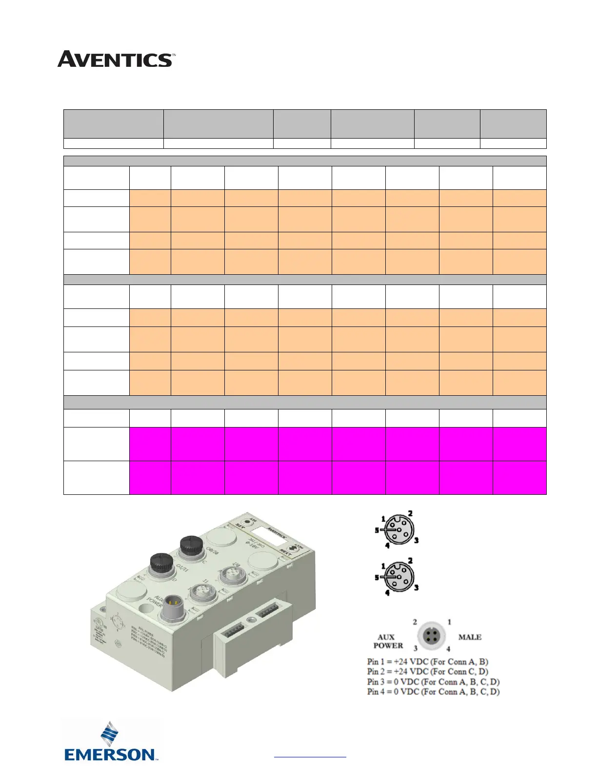
Pin 1 = +10 VDC
Pin 2 = Not Used
Pin 3 = 0 VDC
Pin 4 = Input
Pin 1 = +24 VDC
Pin 2 = Output
Pin 3 = 0 VDC
Pin 4 = Input
 Loading...


