G3 Series EtherCAT
TM
Technical Manual
10-98
Subject to change without notice
www.asco.com/g3
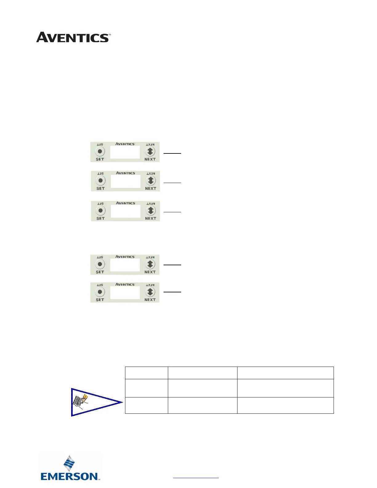
1. Press the SET button to enter the INTERNAL POWER
menu
2. CHANNEL A & B DISABLE
3. Press the NEXT button to scroll through the choices
to enable or disable the feature.
a. ENABLED (Factory Default)
b. DISABLED
c. RETURN (this will return you to the main
menu)
Press the SET button to confirm your choice
4. CHANNEL C & D DISABLE
5. Press the NEXT button to scroll through the choices
to enable or disable the feature.
a. ENABLED (Factory Default)
b. DISABLED
c. RETURN (this will return you to the main
menu)
Press the SET button to confirm your choice
Internal or Aux. Power Select (240-363 Only)
Analog devices connected to the 240-363 can be powered from the Aux. Power supply port
(Internal Power Disabled) or from the module backplane (Internal Power Enabled). This is
selected through the “Internal Power Menu” as shown. Channels A/B and C/D are controlled
independently.
Power Source
Current Limitation for
Module
Current Limitation for connector
Aux Power
8A (From Aux. Power
Conn.)
2.0A / output connector (2.0A Pin 1
to Pin 3)
Internal
Power
1.2A (from Backplane) .15A (Pin 1 to Pin 3)
POWER
ENABLE
DISABLE
DISABLE
ENABLE
 Loading...


