Safety
information
Product
information
Mechanical
installation
Electrical
installation
Getting
started
User Menu A
Commissioning
Advanced
Parameters
Diagnostics Optimization CT MODBUS RTU Technical Data
168 E300 Design Guide
Issue Number: 1
7.9.2 Stop profile brake control
The motor brake control for the Elevator can be controlled either from the E300 Advanced Elevator drive or from the Elevator controller. By default the
drive is set-up to provide a brake control output on control terminal T25. If the Elevator controller manages the motor brake control, the drive can be
configured using T25 Digital I/O 02 Source/Destination (F19) to provide a motor magnetized output. Only once the motor is fully magnetized, does the
drive provide a motor magnetized output which can be used for the brake control in the Elevator controller. Table 7-23 and Table 7-24 describe the
various brake control parameters and settings.
Table 7-23 Brake control digital output parameters
Table 7-24 Brake control parameters
During any drive trip where brake control is being performed, the brake output will become inactive forcing the brake to be closed and preventing
further operation. If the brake control is being carried out by the Elevator controller and a drive trip occurs, the drive ok output will turn Off (0) and the
Elevator controller must apply the motor brake to prevent further operation.
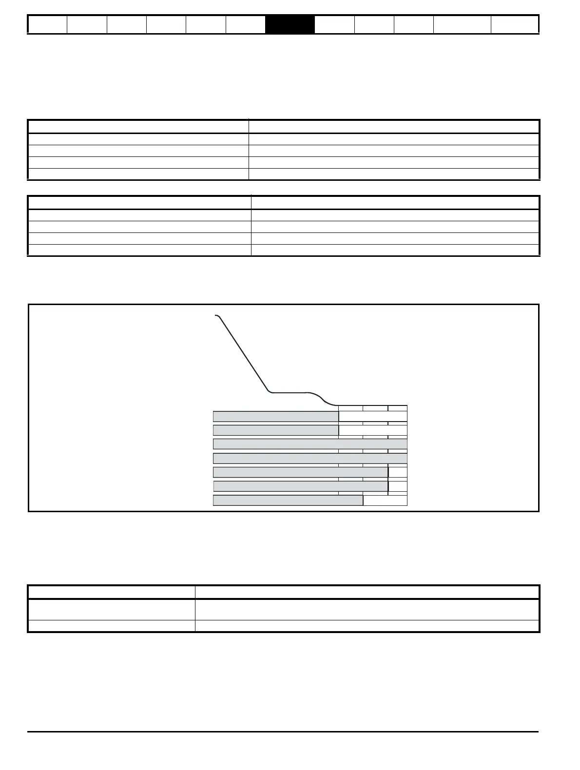
Figure 7-16 Brake control - Closed loop apply
7.9.3 Stop profile, motor contactor control
Following completion of the travel and during the stop sequence the motor brake is applied, after which the symmetrical current limit is ramped down
and the output motor contactors are opened. During the opening of the output motor contactors, the drive’s output should be inactive to avoid
potential damage to both the output motor contactors and the drive as a result of arcing.
Where Motor Contactor Measured Delay Time (B32) is < 50 ms the brake control in Brake Control Apply Delay (D05) should be increased.
Table 7-25 Motor contactor control parameters
Parameter Setting
T25 Digital I/O 02 Source/Destination (F19) Brake Control Output (D03) for brake control output from drive
T25 Digital I/O 02 Source/Destination (F19) Motor Magnetized Indication (D01) for external brake control
T25 Digital I/O 02 State (F04) Digital output state On (1) Off (0)
T25 Digital I/O 2 Invert (F13) Invert digital output on T25
Parameter Detail
Brake Control Output (D03) Brake control output state
Brake Control Apply Delay (D05) Brake apply delay
Brake Apply Low Threshold (D07) Brake control apply low current threshold (Open loop)
Brake Apply Frequency (D07) Brake apply frequency (Open loop)
Parameter Detail
Motor Contactor Measured Delay Time (B32)
Measured time between the end of the travel and the time taken to fully close the output motor
contactors, and remove the Safe Torque Off (STO), Drive enable, value should be > 50 ms
Brake Control Apply Delay (D05) Brake apply delay, increase where Motor Contactor Measured Delay Time (B32) is < 50 ms
Motor contactor
STO, Drive enable
Creep speed
Deflux motor
Motor contactor delay
Speed loop Run Kp
Direction selected
Speed loop Run Ki
Brake control
Brake Control Output ()D03
External motor contactor control
()Creep Stop Jerk G18
()Brake Control Apply Delay D05
Creep Stop Deceleration Rate ()G17
Run Speed Loop P Gain ()I06
Run Speed Loop I Gain ()I07

 Loading...
