Safety
information
Product
information
Mechanical
installation
Electrical
installation
Getting
started
User Menu A Commissioning
Advanced
Parameters
Diagnostics Optimization CT MODBUS RTU Technical Data
240 E300 Design Guide
Issue Number: 1
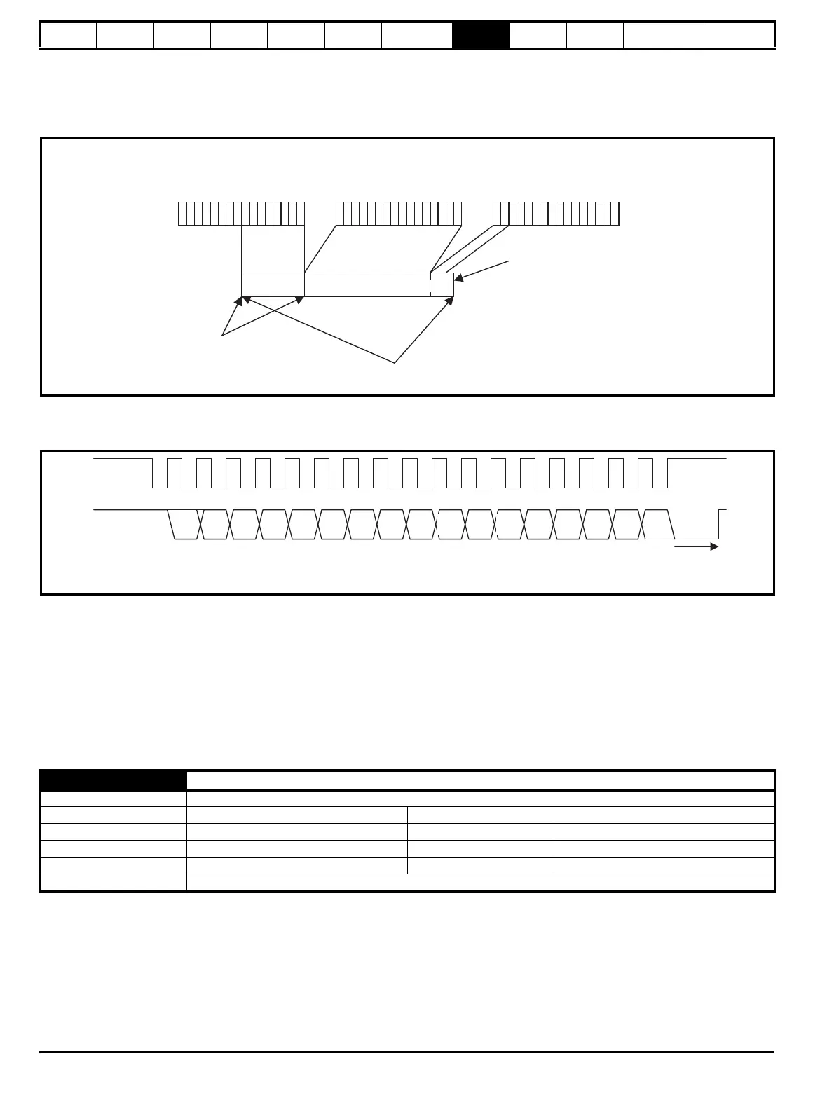
3: SSI
In this mode the B output becomes the clock input and the A output is the data output. If the source position is the Drive position feedback interface
the data from the position feedback interface is transferred to the SSI output register once per sample period defined by Encoder Simulation Sample
Period (C30). An example is given below which shows how the data is aligned.
Figure 8-9 Example of SSI data set-up from Drive position
feedback interface
The SSI output is then clocked out from the register as shown in another example below which includes 15 bits of data.
Figure 8-10 SSI encoder simulation output
It should be noted that the data is shifted out by a clock that is produced by the SSI master connected to the encoder simulation interface as the
interface is emulating an SSI encoder. However, unlike an SSI encoder the position data is not sampled on the first edge of the clock, but is updated
by the drive at the rate defined by Encoder Simulation Sample Period (C30). If the Drive position feedback interface is being used as the source the
power supply alarm bit (PS) is the inverse of the initialized flag in Position Feedback Initialized Indication (C19) related to this interface. The master
can clock out as many bits of data as required, but once the power supply alarm bit has been produced the output will remain low. The SSI interface
reset time (tm) of 20 μs is required so that the interface can detect the end of the transmission and reset itself so that the output data begins again at
the most significant bit. During this period the master should hold the clock line high. The master should not use a clock frequency of less than 50 kHz
or else spurious reset periods may be detected.
If any other parameter is used as the source the most significant M bits of the source parameter are used, where M = Encoder Simulation SSI Comms
Bits (C40) - 1. If the source parameter has less than M bits then trailing zeros are added. The power supply alarm bit is always zero in this mode.
If hardware mode is selected (i.e. Encoder Simulation Mode (C31) = 0) then Encoder Simulation Hardware Divider (C32) defines the divider ratio
between the device connected to the Drive position feedback interface and the output as 1/2 Encoder Simulation Hardware Divider (C32). The
maximum input frequency allowed is 500 kHz, and therefore the maximum output frequency with the highest ratio of unity is 500 kHz.
Drive Encoder
Revolutions (J52)
Drive Encoder
Position (J53)
Drive Encoder Fine
Position (J54)
Encoder Simulation SSI
Turns Bits (C39)=8
Encoder Simulation SSI
Comms Bits (C40)=27
Power supply alarm bit
8 16 2
C32 Encoder Simulation Hardware Divider
Mode RFC-A, RFC-S
Minimum 0 Maximum 7
Default 0 Units ms
Type 8 Bit User Save Update Rate Background read
Display Format Standard Decimal Places 0
Coding RW
10 PS01234567891112131415
tm
Clock from
master
Encoder
simulation data
MS bit

 Loading...
