Safety
information
Product
information
Mechanical
installation
Electrical
installation
Getting
started
User Menu A Commissioning
Advanced
Parameters
Diagnostics Optimization CT MODBUS RTU Technical Data
E300 Design Guide 307
Issue Number: 1
Output phase loss detection can be used to detect a disconnected motor phase if Output Phase Loss Detection Enable (H06) is set to a non-zero
value.
0: Disabled
Output phase loss detection is not active.
1: Enabled
A test is carried out each time the drive is enabled to run to check if all three phases are connected. If the test fails a Out Phase Loss.X trip is initiated
where X indicates which phase is not connected (1 = U, 2 = V, 3 = W). For Open-loop and RFC-A modes a test is also carried out while the drive is
running. If the drive output frequency is above 4 Hz and a phase is disconnected for the time specified by Output Phase Loss Detection Time (H07)
then a Out Phase Loss.4 trip is initiated. It should be noted that if the motor is operating at high speed and flux weakening is active so that the
magnetizing current is below half the rated level then output phase loss will not be detected. If the motor is heavily loaded when a phase is
disconnected it is likely that the motor will stall and the drive output frequency may fall below 4 Hz before output phase loss is detected.
See Output Phase Loss Detection Enable (H06). This parameter has no effect in RFC-S mode.
Input phase loss is detected by monitoring the DC Bus voltage ripple which increases with load. When compared to normal operation, if an input
phase is missing or there is excessive input phase imbalance the d.c. link the ripple level is higher. For frame sizes 7 and above additional input
phase loss detection is provided by direct monitoring of the supply voltages. Unlike the DC Bus voltage ripple based detection which can only operate
when the drive is enabled and on load, the additional input phase loss detection can operate whether the drive is enabled or not. Input Phase Loss
Detection Mode Enable (H08) defines the methods used for input phase loss detection provided by the drive.
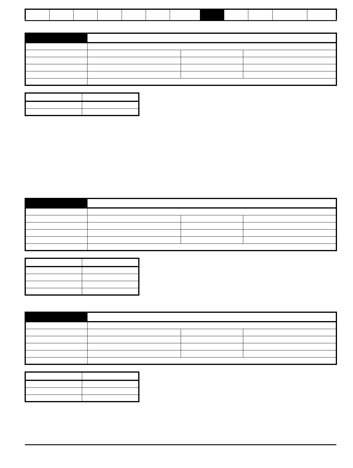
H06 Output Phase Loss Detection Enable
Mode Open-Loop, RFC-A, RFC-S
Minimum 0 Maximum 1
Default 1 Units
Type 8 Bit User Save Update Rate Background read
Display Format Standard Decimal Places 0
Coding RW, TE
Value Text
0 Disabled
1 Enabled
H07 Output Phase Loss Detection Time
Mode Open-Loop, RFC-A
Minimum 0 Maximum 3
Default 0 Units
Type 8 Bit User Save Update Rate Background read
Display Format Standard Decimal Places 0
Coding RW, TE
Value Text
0 0.5 s
1 1.0 s
2 2.0 s
3 4.0 s
H08 Input Phase Loss Detection Mode Enable
Mode Open-Loop, RFC-A, RFC-S
Minimum 0 Maximum 2
Default 0 Units
Type 8 Bit User Save Update Rate Background read
Display Format Standard Decimal Places 0
Coding RW, TE
Value Text
0Full
1 Ripple Only
2 Disabled

 Loading...
