Safety
information
Product
information
Mechanical
installation
Electrical
installation
Getting
started
User Menu A Commissioning
Advanced
Parameters
Diagnostics Optimization CT MODBUS RTU Technical Data
E300 Design Guide 31
Issue Number: 1
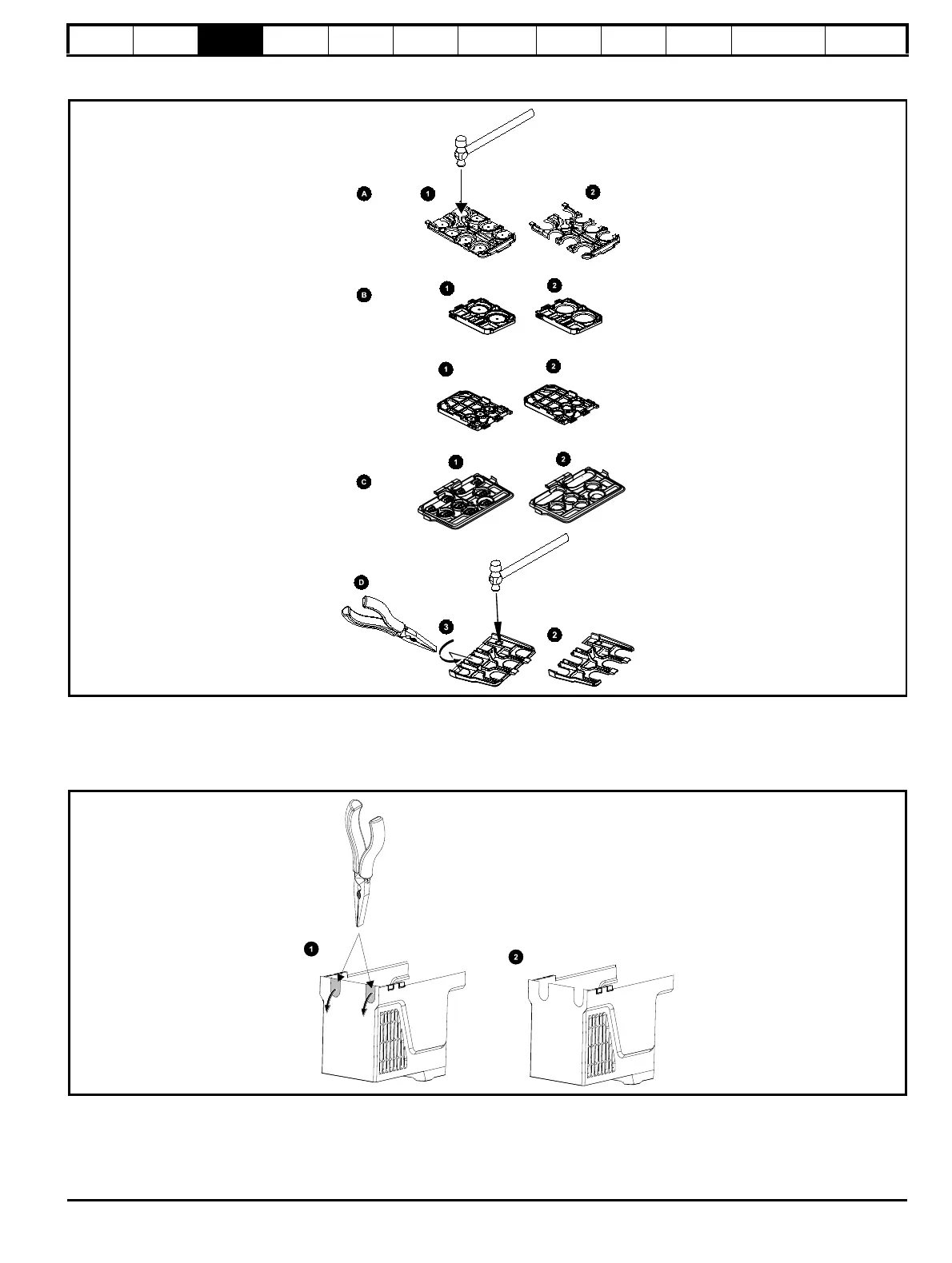
3.3.2 Removing the finger-guard and DC terminal cover break-outs
Figure 3-2 Removing the finger-guard break-outs
A: All sizes, B: Size 5, C: Size 6 D: Size 7
Place the finger-guard on a flat solid surface and remove the relevant break-outs with a hammer as shown (1). For size 7, pliers can be used to
remove the break-outs, grasp the relevant break-out with the pliers and twist as shown (3). Continue until all required break-outs are removed (2).
Remove any flash / sharp edges once the break-outs are removed.
Figure 3-3 Removing the size 3 and 4 DC terminal cover break-outs
Grasp the DC terminal cover break-outs with pliers as shown (1) and pull down in the direction shown to remove. Continue until all required break-
outs are removed (2). Remove any flash / sharp edges once the break-outs are removed. Use the DC terminal cover grommets supplied in the
accessory box to maintain the seal at the top of the drive.

 Loading...
