1592025700 IPROFAMILY 3.5 stp GB 2016.12.07 iPro Series 31/96
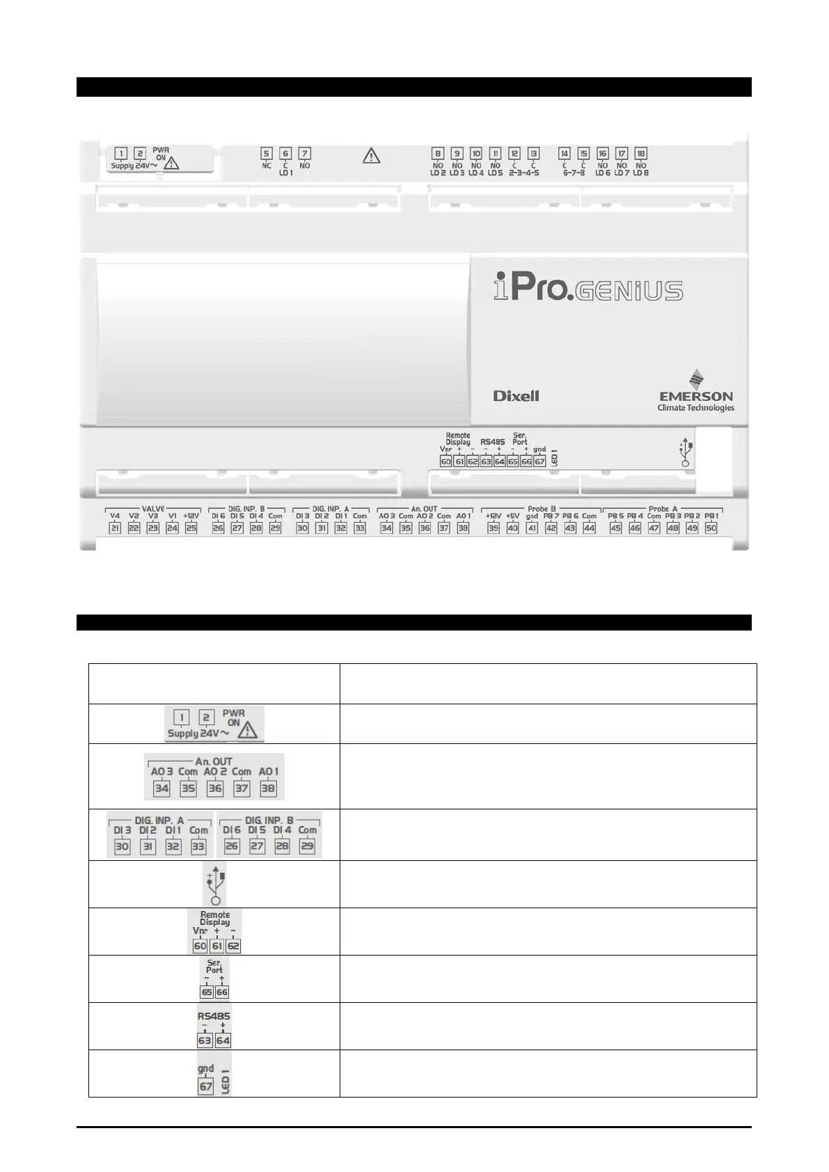
4.4 IPRO.GENIUS (IPG800D RANGES)
4.4.1 Description of the connections
Connector Description
Connector for 24Vac/dc power supply (Black color)
Green LED to indicate the presence of power supply
Connector for the Analog Outputs; depend on the model it can be:
- without PWM:all the three analog output can be used as 0-10Vdc or 4-20mA
- with PWM: only AO1 (38) = OUT and COM (37) = VNR while AO2 and AO3 as
0-10Vdc or 4-20mA
Note: the PWM is available only if the Power Supply is 24Vac.
Potential free not opto-insulated digital inputs.
On request (different Part Number) it is possible to have the Opto-Insulated
digital input but with power supply 24Vac (in this case no potential free
USB port for downloads (BIOS, ISaGRAF® application, maps of parameters,
network configuration, website) and uploads (log files)
Through the adapter “USB-ETH” this port can be used as TCP/IP Ethernet port.
Connector for remote terminal:
- VISOGRAPH, maximum 2 terminals for each XB800
- VISOTOUCH, maximum 1 terminal for each XB800
Serial Port connector; depend on the model it can be:
- LAN (Dixell protocol)
- RS485 MASTER (ModBus RTU)
RS485 connector to connect the device with a monitoring system
- RS485 SLAVE (ModBus RTU)
Ground connection for RS485 and Serial Port
LED1= yellow status led