1592025700 IPROFAMILY 3.5 stp GB 2016.12.07 iPro Series 50/96
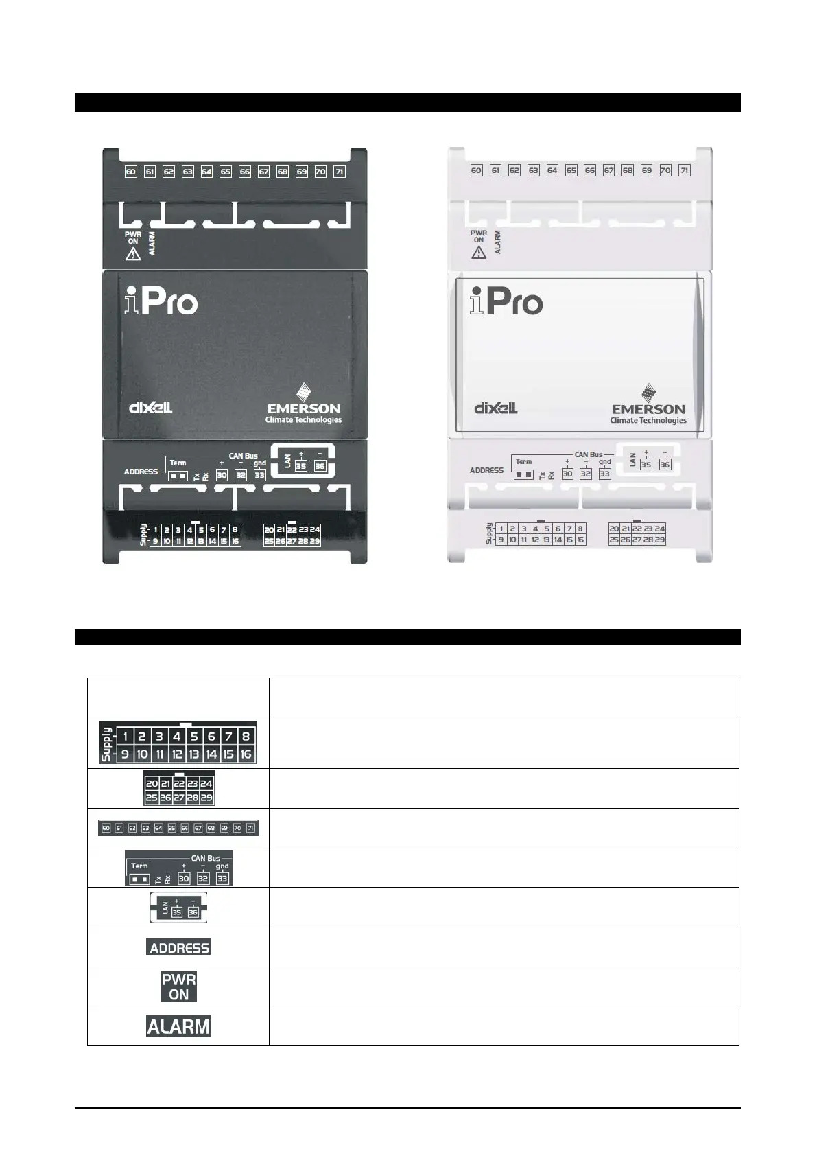
4.8 IPX206D – IPX306D
4.8.1 Description of the connections
Connector Description
Connector for 24Vac/dc power supply
Analogue inputs (Pb1 - Pb5, PbC)
Potential free digital inputs (DI1 - DI3, DIC) or Power supply digital inputs (DI1 – DI3, ID)
Additional power (+5Vdc, +12Vdc, GND)
Analogue outputs (Out1..Out3, GND)
Analogue inputs (Pb6 - Pb7, PbC)
Additional power (+5Vdc, +12Vdc, GND)
Digital relay outputs (depend on the part number of the device):
5 NO relays + 1 changeover relay or 4 NO relays + 1 changeover relay + 1 SSR relay
Rx and Tx LED to indicate that communication is active
LAN serial port connector
Dip-switch to set the address of the device (for CANBUS and LAN communication).
Green LED to indicate the presence of the power supply
See relative paragraph